NUS Soc SWS3005 实时 3D 图形渲染
I. Pre-Knowledge (Phase 1)
Image Formation
How does a realistic graphic form?
Elements of Image Formation
- Objects
- Viewer
- Light sources
- Materials (材质)
- Attributes that govern how light interacts with the materials in the scene
Models
Know about Pinhole Camera
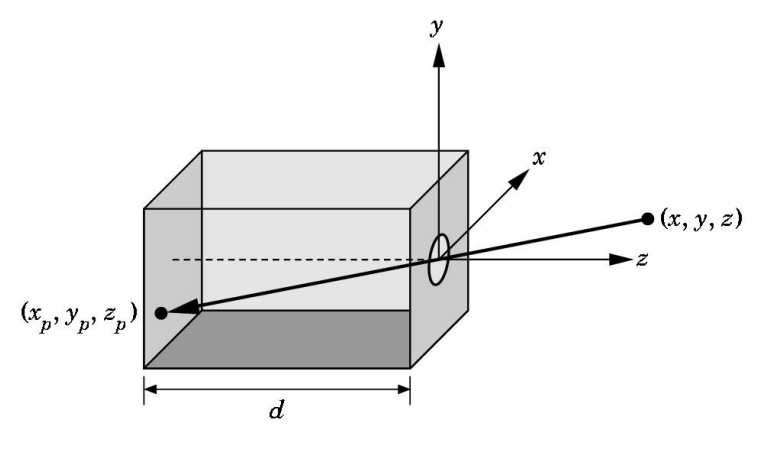
Use trigonometry(三角几何) to find projection of 3D point at $(x, y, z)$
$$
x_p=-dx/z\ \ \ \ y_p=-dy/z\ \ \ \ z_p=-d
$$
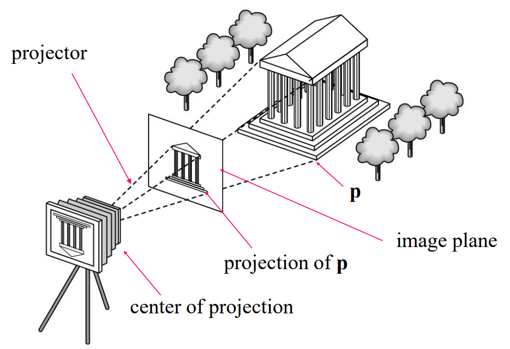
Synthetic Camera Model (合成相机模型)
Luminance and Color Images (光线与颜色的映射)
- Luminance Image
- Monochromatic(单色)
- Values are gray levels
- Analogous to working with black and white film or television
- Monochromatic(单色)
- Color Image
- Has perceptional attributes of hue(色相), saturation(饱和度), and lightness
↓
- Representation of Color
- Additive color: Form a color by adding amounts of three primaries(RGB)
- E.g. CRTs, projection systems, positive film
- Subtractive color: Form a color by filtering white light with Cyan (C), Magenta (M), and Yellow (Y) filters
- Noted: Cyan = –Red; Magenta = –Green; Yellow = –Blue
- Additive color: Form a color by adding amounts of three primaries(RGB)
Graphics System Design
A graphics system has two main components
- Application Programmer Interface (API)
- For specifying the scene
- objects, materials, viewer, lights
- For configuring/controlling the system
- For specifying the scene
- Renderer
- Renders the images
- Using scene info and system configuration
- Renders the images
Rendering Approaches
- Ray tracing: follow rays of light from center of projection until they are absorbed by objects or go off to infinity
- 符合物理解释,泛用性广;但是速度慢,性能低
- Radiosity: Energy based approach
- 非常慢且不泛用
Practical Approach
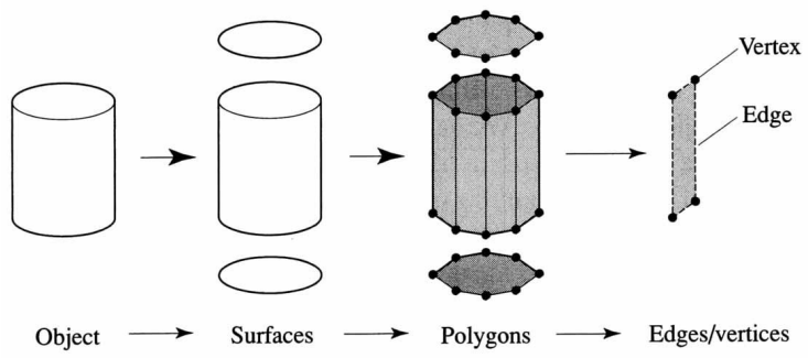
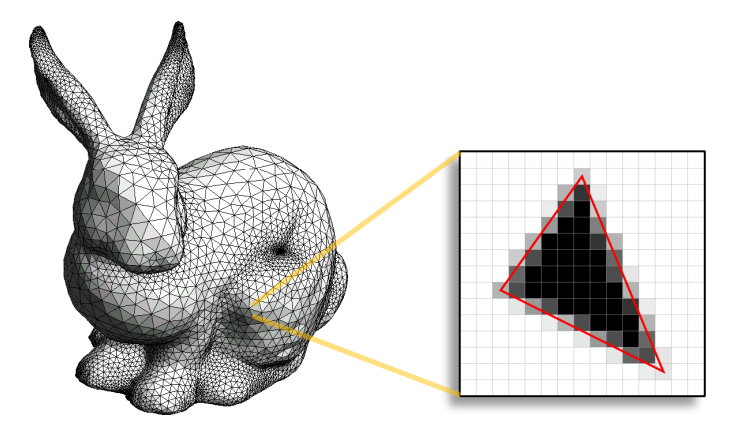
- Polygon Rasterization(多边形光栅)
3D 物体可以近似地表示为平面多边形刻面 (planar polygonal facets) 的网或网格
 |
 |
Pipeline architecture
The pipeline consists of stages that each primitive (e.g. polygon) must go through
1 | Vertices -> |Vertex processor| -> |Clipper and primitive assembler| -> |Rasterizer| |
(i) Vertex Processing
- Much of the work in the pipeline is in converting object representations from one coordinate system to another
- Object coordinates
- Camera (eye) coordinates
- Screen coordinates
- Also computes vertex colors
(ii) Projection
- Projection is the process that combines the 3D viewer with the 3D objects to produce the 2D image
- Perspective projections: all projectors meet at the center of projection
- Parallel projection: projectors are parallel, center of projection is replaced by a direction of projection
(iii) Clipping
- Simulate a virtual camera to clip the images
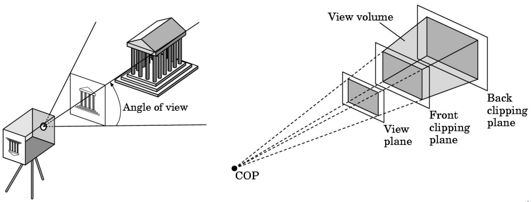
(iv) Rasterization
- Rasterizer produces a set of fragments for each object
- Fragments are “potential pixels”
- Have a location in frame bufffer
- Color and depth attributes
Fragment Processing
- Fragments are processed to determine the color of the corresponding pixel in the frame buffer
- Colors can be determined by texture mapping or interpolation(插值) of vertex colors
- Fragments may be blocked/occluded(阻塞) by other fragments closer to the camera
- Using Hidden-surface removal
API Contents
- Recall: Functions that specify what we need to form an image
- Objects
- Viewer
- Light Source(s)
- Materials
Object Specifications
- Most APIs support a limited set of primitives including
- Points (0D object)
- Line segments (1D objects)
- Polygons (2D objects)
- Some curves and surfaces
- Quadrics
- Parametric polynomials
- All are defined through locations in space or vertices
Camera Specification
- Six degrees of freedom
- Position of center of lens
- Orientation
- Lens
- Film size
- Orientation of film plane
Lights and Materials
- Types of lights
- Point sources vs distributed sources
- Spot lights
- Near and far sources
- Color properties
- Material properties
- Absorption: color properties
- Scattering
- Diffuse
- Specular
II. Elementary OpenGL Programming
OpenGL Libraries
Core Library
- OpenGL core library
- OpenGL32 on Windows
- GL on most unix/linux systems (
libGL.a)
- OpenGL Utility Library ( GLU )
- Provides functionality in OpenGL core but avoids having to rewrite code
- Links with window system
GLXfor X window systemsWGLfor WindowsAGLfor Macintosh
GLUT / FreeGLUT Libraries
- GLUT = OpenGL Utility Toolkit
- Not part of OpenGL
- Provides functionality common to all window systems
- Open a window
- Get input from mouse and keyboard
- Menus
- Event-driven
- Code is portable but GLUT lacks the functionality of a good toolkit for a specific platform
- No slide bars
- FreeGLUT
Software Organization
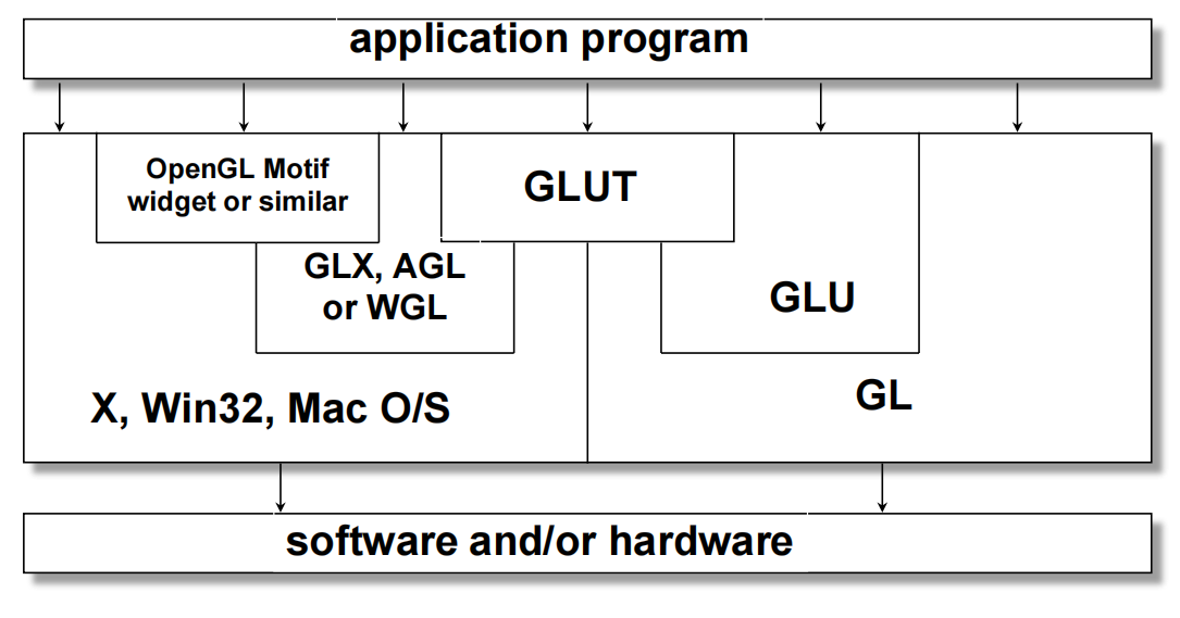
Basic OpenGL Rendering Pipeline
- To render a primitive using OpenGL, the primitive goes through the following main stages:
- Goal: Turning primitive into pixels
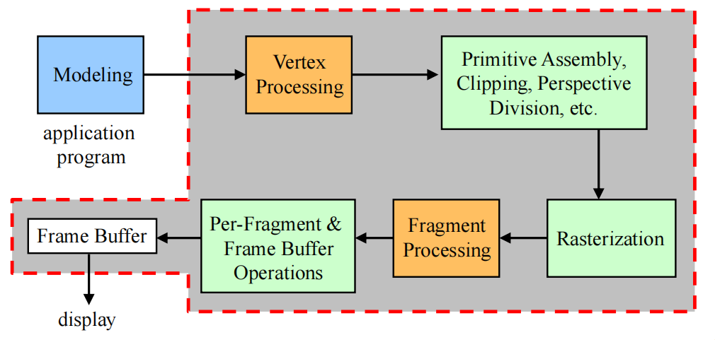
OpenGL Functions
- Specify primitives
- E.g. points, line segments, triangles, quadrilaterals, polygons
- Specify vertex attributes
- E.g. color, normal vector, material, texture coordinates
- Specify transformations
- E.g. modeling, viewing
- Control (
GLUT) - Input (
GLUT) - Query: “ask for the state of object” etc.
OpenGL State
-
OpenGL is a state machine
-
OpenGL functions are of two types
- Primitive generating
- Can cause output if primitive is visible
- How vertices are processed and appearance of primitive are controlled by the state
- State changing
- Transformation functions
- Attribute functions
- Primitive generating
Simple Concept
Examples
1 |
|
This code is to draw a white square in black background.
Event Loop
Note that the program defines a display callback function named mydisplay
- Every GLUT program must have a display callback
- The display callback is executed whenever OpenGL decides the display must be refreshed
- For example, when the window is opened
- The main function ends with the program entering an event loop
Program Structure
- Most OpenGL programs have a similar structure that consists of the following functions
main():- defines the callback functions
- opens one or more windows with the required properties
- enters event loop (last executable statement)
init(): sets the state variables- Viewing
- Attributes
- callbacks
- Display callback function
- Input and window functions
Then we’re going to see an explicit form of
Example
main()
1 |
|
glutInit—— allows application to get command line arguments and initializes systemgluInitDisplayMode—— requests properties for the window (the rendering context)- RGB color
- Single buffering
- Properties logically ORed together
glutWindowSize—— in pixelsglutWindowPosition—— from top-left corner of displayglutCreateWindow—— create window with title “simple”glutDisplayFunc—— display callbackglutMainLoop—— enter infinite event loop
init()
1 | void init() |
- Coordinate Systems (have a rough knowing)
- object coordinates (3D)
- world coordinates (camera)
- window coordinates
- About OpenGL Camera
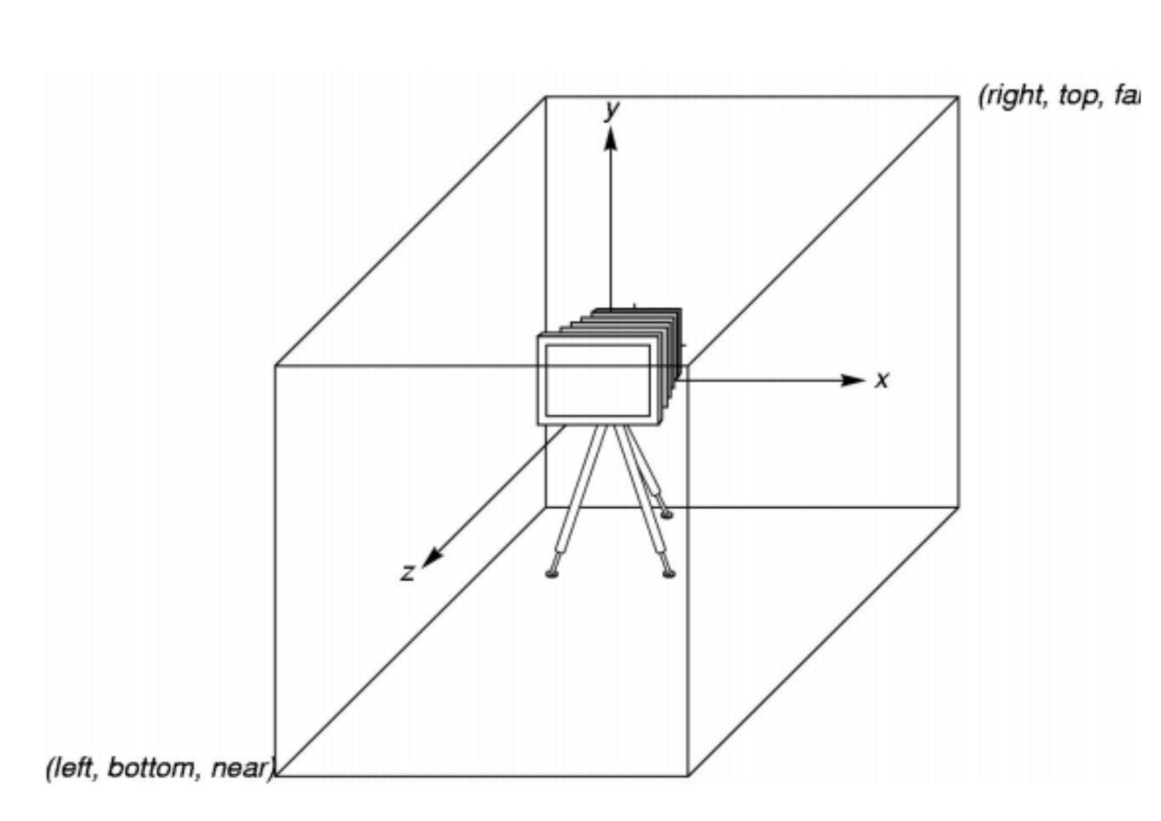
- Orthographic Viewing and Transformation
- In the default orthographic view, points are projected forward along the $z$ axis onto the plane $z = 0$
- In OpenGL, projection is carried out by a projection matrix (transformation)
- There is only one set of transformation functions so we must set the matrix mode first
glMatrixMode(GL_PROJECTION)
- Transformation functions are incremental so we start with an identity matrix and alter it with a projection matrix that gives the view volume
glLoadIdentity();glOrtho(-1.0, 1.0, -1.0, 1.0, -1.0, 1.0);
glOrtho(left, right, bottom, top, near, far)is used to determine the projection area.- If the application is in 2D, we can use the function
gluOrtho2D(left, right, bottom, top)
Here is an example of how to draw a projection on 2D windows.
Because a projection from 3D to 2D is in OpenGL-Primitives (I show below), so we only need to paint it out.
1 | void mydisplay() |
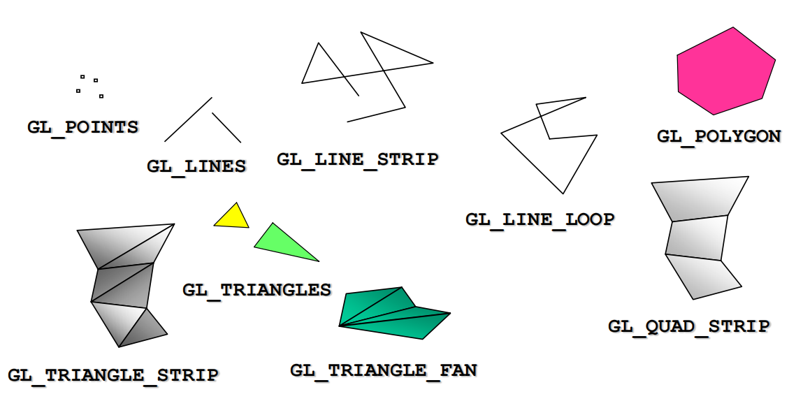
Other methods of OpenGL
glShadeModel()to set the color rendering to beGL_SMOOTH(渐变) orGL_FLAT(单色).glViewport(x, y, w, h)to set the viewport of windows.
3D OpenGL
Three-Dimensional Applications
- In OpenGL, 2D applications are a special case of 3D graphics
- Going to 3D
- Not much changes
- Use
glVertex3*() - Have to worry about the order in which polygons are drawn or use hidden-surface removal (occlusion problem)
- Polygons should be simple, convex, flat
Gasket Program
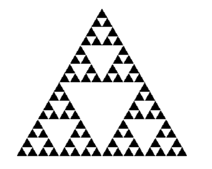
- Consider the filled area (black) and the perimeter (the length of all the lines around the filled triangles)
- As we continue subdividing
- the area goes to zero (< 2D)
- but the perimeter goes to infinity (> 1D)
- This is not an ordinary geometric object
- It is neither one- nor two-dimensional
- It is a fractal (fractional dimension) object
- Approximately 1.585 D
How to do in program?
Using algorithm of Recursion!
- Design
display()andmyinit()
1 | void display() |
- Then set parameter and callback function in
main()
1 | int main(int argc, char **argv) |
Move to 3D triangle
- Add an extra vertex to form tetrahedra
- Then we can do like 2D triangle subdivision
But we have to deal with Hidden-Surface Removal !!
-
- OpenGL uses a hidden-surface removal method called the z-buffer algorithm that saves depth information as objects are rendered so that only the front objects appear in the image.
Using the z-buffer Algorithm
Requested in main()
1 | glutInitDisplayMode(GLUT_SINGLE | GLUT_RGB | GLUT_DEPTH) |
Enabled in init()
1 | glEnable(GL_DEPTH_TEST) |
Cleared in the display callback
1 | glClear(GL_COLOR_BUFFER_BIT | GL_DEPTH_BUFFER_BIT) |
Surface vs. Volume Subdivision
- In our example, we subdivided the surface of each face
- We could also subdivide the volume using the same midpoints
- The midpoints define four smaller tetrahedrons, one for each vertex
- Keeping only these tetrahedrons removes a volume in the middle
- Good programming exercise
III. Input & Interaction
Concept
-
Graphical Input
- Devices can be described either by
- Physical properties
- Mouse, Keyboard, Trackball, etc.
- Logical properties: What is returned to program via API
- A position
- An object identifier
- Physical properties
- Devices can be described either by
-
Trigger and Measure
- Input devices contain a trigger which can be used to send a signal to the operating system
- Button on mouse
- Pressing or releasing a key
- When triggered, input devices return information (their measure) to the system
- Mouse returns position information
- Keyboard returns ASCII code
- Input devices contain a trigger which can be used to send a signal to the operating system
-
Event Mode
- Each trigger generates an event whose measure is put in an event queue which can be examined by the user program

-
Event Type
- Window: resize, expose, minimize
- Mouse: click one or more buttons
- Motion: move mouse
- Keyboard: press or release a key
- Idle: non-event (无输入时的活动)
- Define what should be done if no other event is in queue
-
Recall: callbacks
- Define a callback function for each type of event the graphics system recognizes
- E.g.
glutMouseFunc(mymouse)wheremymouseis a mouse callback function.
-
GLUT recognizes a subset of the events recognized by any particular operation system :
glutDisplayFuncglutMouseFuncglutReshapeFuncglutKeyboardFuncglutIdleFuncglutMotionFunc,glutPassiveMotionFunc
GLUT Event Loop
- Recall: the last statement in
main()for a program using GLUT must beglutMainLoop(); - In each pass through the event loop, GLUT
- looks at the events in the queue
- execute each event if the corresponding callback function is defined.
Important before talking about callbacks:
- The form of all GLUT callbacks is fixed
- So we must use globals (全局变量) to pass information to callbacks
Display Callback
- When windows are refreshed, apply display callbacks
glutDisplayFunc(mydisplay)inmain()glutPostRedisplay()to avoid multiple display in one single pass through the event loop- set a “flag” at the end of the event loop.
- GLUT checks it and display callback function is executed.
- Then what’s inside
mydisplay?glClear()to clear the window- Use Double Buffer to avoid partial drawn
- Front Buffer: one that is displayed but not written to
- Back Buffer: one that is written to but not displayed
glutInitDisplayMode(GLUT_RGB | GLUT_DOUBLE)declare inmain()to request a double buffer- At the end of display callback buffers are swapped.
1 | void mydisplay() |
Idle Callback
- The idle callback is executed whenever there are no events in the event queue
glutIdleFunc(myidle)inmain()- Useful for animation
1 | void myidle() { |
Mouse and Keyboard Callbacks
glutMouseFunc(mymouse)inmain()void mymouse(GLint button, GLint state, GLint x, GLint y)to define mouse callbacks- Buttons:
GLUT_LEFT_BUTTON,GLUT_MIDDLE_BUTTONorGLUT_RIGHT_BUTTON - States:
GLUT_UPorGLUT_DOWN - Cursor Position: top-left corner is (0,0) [Others depend on winsize]
- Buttons:
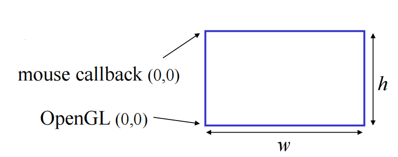
$$
y_{\text{OpenGL}}= h-1-y_{text{win}}
$$
E.g. To draw a square when mouse click
1 | void mymouse(int btn, int state, int x, int y) |
-
We can draw squares (or anything else) continuously as long as a mouse button is depressed by using the motion callback
glutMotionFunc(drawSquare)
-
We can draw squares without depressing a button using the passive motion callback (用于鼠标没按下但在移动时的操作)
glutPassiveMotionFunc(drawSquare)
-
Keyboard is almost the same
glutKeyboardFunc(mykey)void mykey(unsigned char key, int x, int y)
E.g.
1 | void mykey(unsigned char key, int x, int y) |
Others:
GLUT defines the special keys in
glut.h
- Function key 1:
GLUT_KEY_F1- Up arrow key:
GLUT_KEY_UPAlso check modifiers
GLUT_ACTIVE_SHIFT,GLUT_ACTIVE_CTRL,GLUT_ACTIVE_ALTis depressed usingglutGetModifiers()
Reshape Callback
glutReshapeFunc(myreshape)inmain()void myreshape(int w, int h)
E.g.
1 | void myReshape(int w, int h) |
Menu
1 | // main() |
1 | void mymenu(int id) |
Other Functions
- Dynamic Windows
- Create and destroy during execution
- Subwindows
- Multiple Windows
- Changing callbacks during execution
- Timers (look up glutTimerFunc)
- Useful for controlling speed of animation
- Portable fonts
- glutBitmapCharacter
- glutStrokeCharacter
IV. Geometric Objects & Transformations
- Basic elements
- Scalars
- Vectors
- Points
- Basic primitives
- Line segments
- Polygons
Representation
- Introduce
- coordinate systems for representing vector spaces
- frames for representing affine spaces(仿射空间)
- Discuss change of frames and bases
- Introduce homogeneous coordinates
Coordinate Systems
Recall: Linear Algebra
- basis: $v_1,v_2,…,v_n$
- a vector written as $v=\alpha_1 v_1+\alpha_2 v_2 + \cdots + \alpha_n v_n$
- the coordinate of $v$ in this basis is ${ \alpha_1,\alpha_2, \cdots , \alpha_n }$
Frame
Def. A frame is a system with a single point(origin $P_0$) and a basis vector in an affine space.
$$
P=P_0 + \beta_1 v_1 + \beta_2 v_2 + \cdots + \beta_n v_n
$$
Homogeneous Coordinates
E.g. for a 3 * 3 space, the 3 * 3 matrices cannot used for translation(平移), because vectors have no position.
- We extend the $3\times 3$ point to 4-dimension: $(x,y,z) \rightarrow (x,y,z,1)$
- and a $4\times 4$ matrix can represent translation, rotation and scaling and shear
- using matrix(a template) below, we can maintain $w=0$ for vectors and $w=1$ for points for orthographic viewing .
$$
\left( \begin{array}{c}
a & b & c & tx \
d & e & f & ty \
g & h & i & tz \
0 & 0 & 0 & 1
\end{array}\right)
$$
E.g. For a 3D point $(x,y,z)$ , its homogeneous coordinate is $P_h = (x,y,z,1)$ . To translate it, we define a matrix:
$$
\left( \begin{array}{c}
1 & 0 & 0 & tx \
0 & 1 & 0 & ty \
0 & 0 & 1 & tz \
0 & 0 & 0 & 1
\end{array}\right)
\left( \begin{array}{c}
x \ y \ z \ 1
\end{array}\right) =
\left( \begin{array}{c}
x+ tx \ y+ ty \ z+ tz \ 1
\end{array}\right)
$$
- More generally, homogeneous coordinates are represented as $p=[ wx,wy,wz,w ]^T$
Transformation
-
Affine Transformation: Line preserving
-
Translation: move points
- $P’=P+d$ where $d=[d_x, d_y, d_z, 0]^T$
-
Recall for Linear Algebra: Some linear transformation:
- Rotation (2D)
- Scaling
- Reflection
try to remember their transformation matrices.
Inverses
- Translation: $\textbf{T}^{-1}=\textbf{T}(-d_x, -d_y, -d_z)$
- Rotation: $\textbf{R}^{-1}(\theta)=\textbf{R}(- \theta)$
- Noted that only $cos(\theta)$ on orthogonal entry
- Scaling: $\textbf{S}^{-1}(s_x, s_y, s_z)=\textbf{S}(1/s_x, 1/s_y, 1/s_z)$
Examples
Rotation About a Fixed Point Other than the Origin:
- Move fixed point to origin
- Rotate
- Move fixed point back
$$
\textbf{M}=\textbf{T}(p_f)\textbf{R}(\theta)\textbf{T}(-p_f)
$$
(bu)
OpenGL Transformations
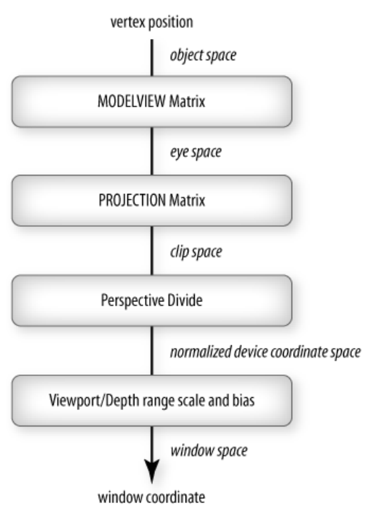
-
Recall:
glMatrixMode(GLenum mode)to change the mode of matrix calculation- when doing transformation, use
GL_MODELVIEWstate
- when doing transformation, use
-
For all CTM(Current Transformation Matrix) Operations, our CPP Code must load identity matrix first:
1 | glMatrixMode(GL_MODELVIEW); |
- Beware of using post-multiplications (the later operations should be multipled to result matrix $\textbf{C}$ earlier)
- E.g. Rotation About a Fixed Point: $\textbf{C}=\textbf{T}^{-1}\textbf{R}\textbf{T}$
- Other Transformation Matrix specifying
- rotation:
glRotatef(theta, vx, vy, yz) - translation:
glTranslatef(dx, dy, dz) - scale:
glScalef(sx, sy, sz)
- rotation:
V. Camera & Viewing
Computer Viewing
- 2 attributes to define the viewing:
- Positioning the camera
- Setting the model-view matrix
- Selecting a lens
- Setting the projection matrix
- Perspective or orthographic / view volume / clipping volume …
- Positioning the camera
Specify Different Space

- Local / Modeling / Object Space
- Each object model has its own local coordinate frame
- World Space (类似全局空间)
- Lights and Camera pose are defined in this space
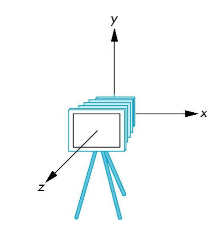
- Camera Space / View Space / Eye Space
- Camera is located at the origin
- Looking in negative $z$ direction
- $+y$-axis is the “up-vector”
Initially the world and camera frames are the same.
To specify camera pose, we need to specify the camera coordinate frame with respect to the world coordinate frame.
View Transformation
1 | glLookAt( eyex, eyey, eyez, |
- 通过 eye 和 at 求出前向量
$$
\text{forward}=\frac{\text{at} - \text{eye}}{|\text{at} - \text{eye}|}
$$
- 通过 forward 和 up 求出右向量
$$
\text{side}=\frac{\text{forward} \times \text{up}}{|\text{forward} \times \text{up}|}
$$
- 然后就能得到修正后的上向量
$$
\text{up’}= \text{forward} \times \text{side}
$$
- 求出三个向量后就能确定 camera 的位置和 pose 了
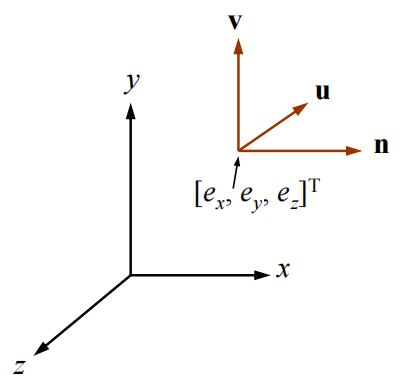
- Suppose the camera has been moved to the location $[e_x, e_y, e_z]^T$, and its $x_c$, $y_c$, $z_c$ axes are the unit vectors $\textbf{u}$, $\textbf{v}$, $\textbf{n}$, respectively, then
$$
\textbf{M}_{\text{view}}=
\left[ \begin{array}{c}
u_x & u_y & u_z & 0 \
v_x & v_y & v_z & 0 \
n_x & n_y & n_z & 0 \
0 & 0 & 0 & 1
\end{array}\right]
\cdot
\left[ \begin{array}{c}
1 & 0 & 0 & -e_x \
0 & 1 & 0 & -e_y \
0 & 0 & 1 & -e_z \
0 & 0 & 0 & 1
\end{array}\right]
$$
▪ Note that $[e_x, e_y, e_z]^T$ and $\textbf{u}$, $\textbf{v}$, $\textbf{n}$ are all specified with respect to the world frame
Projection —— Defining the View Volume
- For orthographic projection, use
glOrtho() - For perspective projection, use
glFrustum()
OpenGL Orthographic Projection
- The glOrtho() function then generates a matrix that linearly maps the view volume to the canonical view volume, where
- (left, bottom, –near) is mapped to (–1, –1, –1)
- (right, top, – far) is mapped to (1, 1, 1)
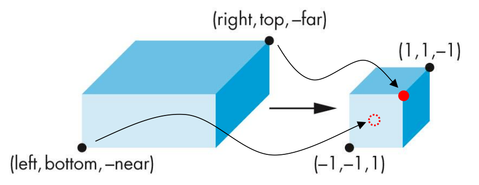
正投影,能较真实地反映物体大小,物体显示的大小不会因视角变化改变。常用于CAD设计、地图绘制、2D游戏等不需要表现深度感的场景。
OpenGL Perspective Projection
glFrustum( left, right, bottom, top, near, far )- The
glFrustum()function allows (off-center) non-symmetric view volume
- The
- Often, we want a symmetric view volume. We can use
gluPerspective( fovy, aspect, near, far );
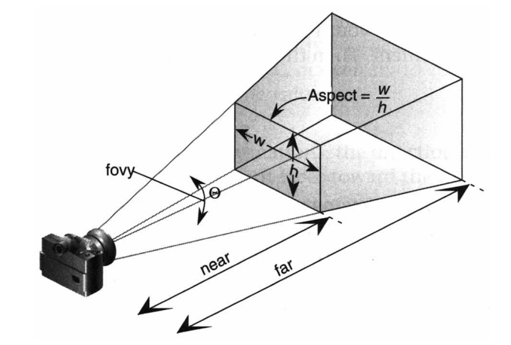
透视投影,有深度感,近大远小。常用于3D游戏、虚拟现实、建筑可视化等需要真实感的场景。
Principle of Perspective Projection
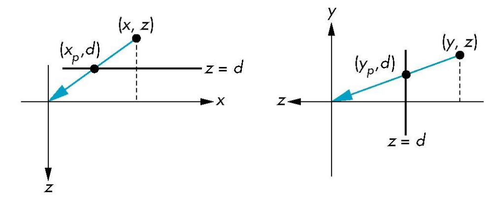
- Center of projection at the origin
- Projection plane is $z = d$, $d < 0$
$$
x_p=\frac{x}{z/d}\ \ \ \ y_p=\frac{y}{z/d}\ \ \ \ z_p=d
$$
- Consider $p=Mq$ where
$$
p=
\left[ \begin{array}{c}
x \ y \ z \ z/d
\end{array}\right] \ \ \ \ M=
\left[ \begin{array}{c}
1 & 0 & 0 & 0 \
0 & 1 & 0 & 0 \
0 & 0 & 1 & 0 \
0 & 0 & 1/d & 0
\end{array}\right] \ \ \ \ q=
\left[ \begin{array}{c}
x \ y \ z \ 1
\end{array}\right]
$$
- If we scale $p$ , then we get the projection point on plane $z=d$ .
VI. Rasterization
Recall for OpenGL Rendering Pipeline
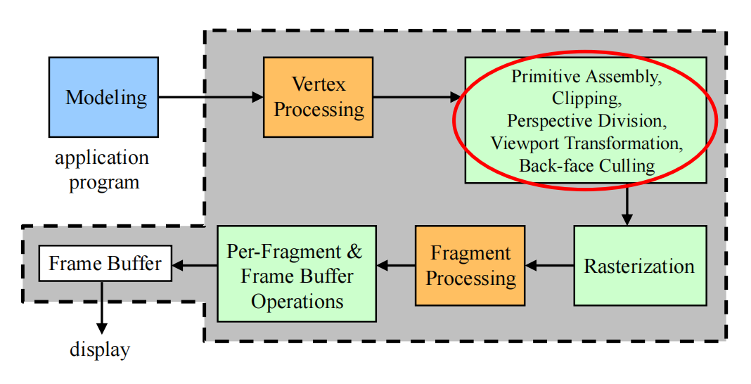
Primitive Assembly, etc.
- Primitive assembly
- Vertex data is collected into complete primitives
- Necessary for clipping and back-face culling
- Clipping
- Perspective division (Object Oriented)
- To normalized device coordinate (NDC) space
- Viewport transformation (Viewer Oriented)
- To window space
- Include depth range scaling
- Back-face culling
Rasterization & Fragment Processing
- Attribute values at fragments are computed by interpolating attribute values assigned to vertices
- Interpolation is performed in window space (2D)
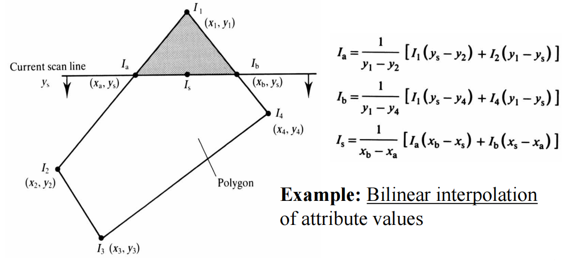
- Each generated fragment is processed to determine the color of the corresponding pixel in the frame buffer
- Fragment color can be modified by texture mapping (纹理映射)
- Texture access (using interpolated texture coordinates)
- Access texture map using texture coordinates
- Texture application
- Texture color can be combined with the fragment color of the primitive
- Texture access (using interpolated texture coordinates)
Per-Fragment Operations
- Fragment is discarded if it is blocked (occluded) by the corresponding pixel already in the frame buffer
- Z-buffer hidden-surface removal
- Fragment may be blended with the corresponding pixel already in the frame buffer
- Blending
Let’s talk about something important !!!
Clipping
To clip out primitives that are outside the view volume
Clipping 2D Line Segments
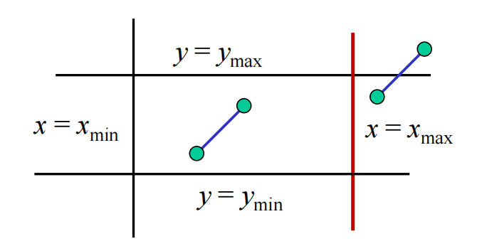
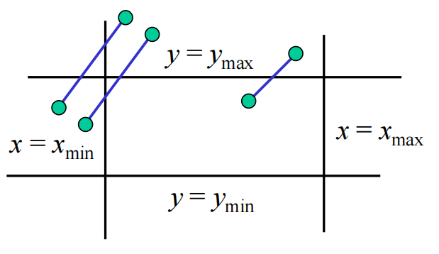
Cohen-Sutherland Algorithm
- Using edge table
 |
|
 |
|
Using Outcode
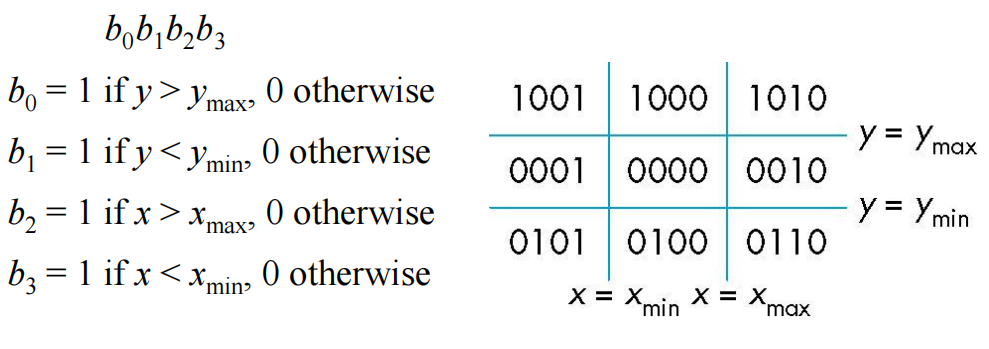
E.g. Suppose a line $AB$ with endpoints $A$ and $B$ .
-
If $\text{outcode}(A)=\text{outcode}(B)=0$ , accept the segment
-
If $\text{outcode}(A)=0$ , $\text{outcode}(B)\not= 0$ ,
- Compute intersection
- Location of $1$ in outcode($B$) determines which edge to intersect with
- If outcode($B$) has two $1$'s, then need to do two intersections
-
If $\text{outcode}(A)$ & $\text{outcode}(B) \not= 0$ , reject the segment
-
If $\text{outcode}(A)$ & $\text{outcode}(B) = 0$ , but neither of them are $0$ ,
- Shorten line segment by intersecting with one of sides of window
- Compute outcode of intersection (new endpoint of shortened line segment)
- Re-execute algorithm
-
When it goes to 3D, we can use 6-bit outcode to represent 6 faces of the window.
Polygon Clipping
Problems of polygon clipping: may generate multiple polygons.
Solution: For concave polygons, use tessellation function(镶嵌函数) in
GLUto change it to multiple convex polygons.
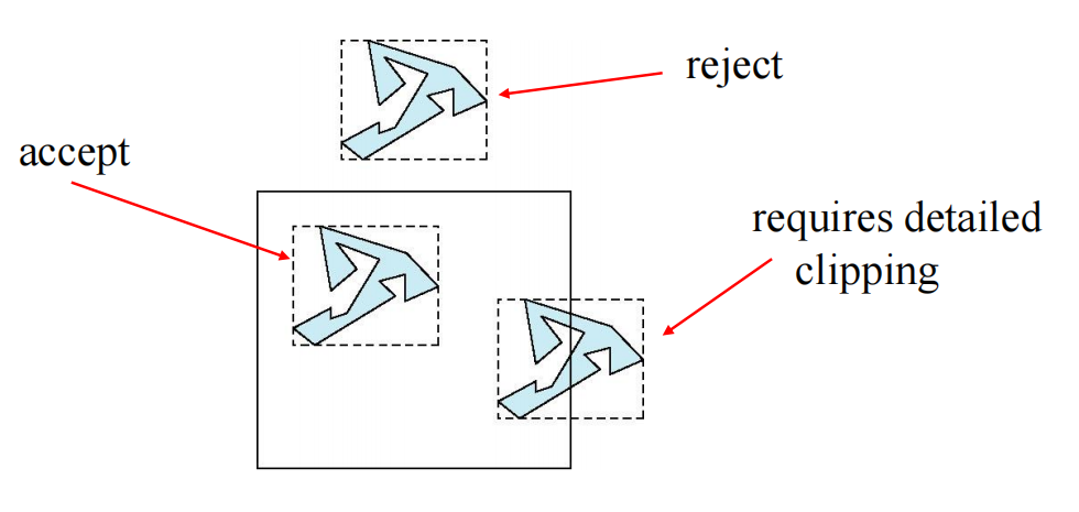
- simple way: set axis-aligned bounding box(AABB) for simple calculation.
Rasterization
Scan Conversion of Line Segments
- Key thought: A binary decision problem on how the next pixel lies based on the previous pixel.
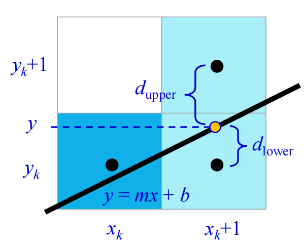
- On the next point: $y=m(x_k + 1) + b$
- $d_\text{lower} = y-y_k$
- $d_\text{upper}=(y_k+1)-y$
$$
\begin{align}
p_k&=\Delta x(d_\text{lower} - d_\text{upper}) \
&=2x_k \Delta y - 2y_k \Delta x + c
\end{align}
$$
where $c=2\Delta y + \Delta x (2b - 1)$ is an integer constant .
-
If $p_k > 0$ , plot upper pixel
-
If $p_k < 0$ , plot lower pixel
-
We can incrementally compute $p_{k+1}$ from $p_k$
- If $p_k > 0$ , $p_{k + 1} = p_k + 2\Delta y – 2\Delta x$
- If $p_k < 0$, $p_{k + 1} = p_k + 2\Delta y$
- where $p_0=2\Delta y - \Delta x$
Scan Conversion of Polygons
Scan-Line Fill — Interpolation
- $C_1$ $C_2$ $C_3$ specified by glColor or by vertex shading (lighting computation)
- $C_4$ determined by interpolating between $C_1$ and $C_3$
- $C_5$ determined by interpolating between $C_2$ and $C_3$
- Interpolate between $C_4$ and $C_5$ along span
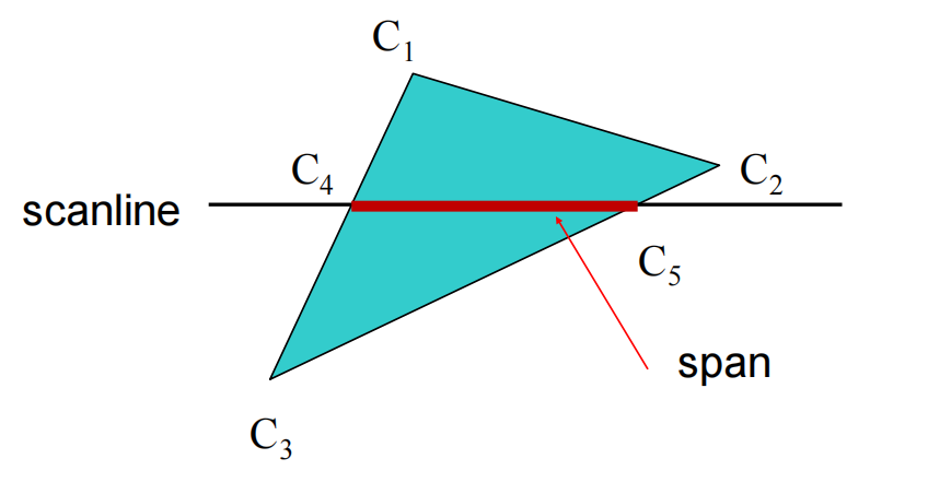
So what we need to do in this algorithm is calculating :
- points intersact with scan-line (Recall Bresenham’s Algorithm)
- which polygons lie on this pixel (多边形扫描转换,边表,活动边表)
Hidden-Surface Removal
- Painter’s Algorithm
- Fill the objects at the back first, then cover with the front objects
- Depth Sorting
- Need $O(n^2)$ at worst
Back-Face Culling
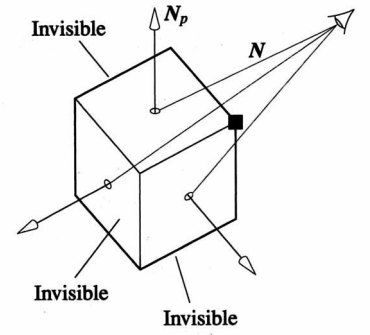
- Polygons is back-facing if $\textbf{N}_p \cdot \textbf{N} <0$
- In OpenGL, we can simply enable culling
- By default, polygon vertices must be provided in counter clockwise order
- But may not work correctly for non-convex polygon
Z-Buffer
- Key thought: Exchange time with space
- Use a z-buffer (depth buffer) to store the depth of the closest object at each pixel found so far
Summary

- Viewing this pipeline again:
- Using back-face culling to remove hidden-surface
- Using scan conversion to do rasterization
- Using z-buffer to test the per-fragment
- At the end, output frame buffer.
VII. Illumination
Local Reflection vs Global Illumination
- Local reflection
- Considers relationship between a light source, a single surface point, and a view point
- No interaction with other objects
- Global illumination
- Considers all light sources and surfaces
- Inter-reflections and shadows
Phong Illumination Equation
$$
I_{\text{Phong}}=k_a i_a + \sum_{m \in \text{lights}} \left(k_d (\textbf{L}m \cdot \textbf{N}) i{m,d} + k_s (\textbf{R}m \cdot \textbf{V})^{\alpha} i{m,s} \right)
$$
where :
- $k_a$ 表示环境光反射系数,常数
- $k_d$ 表示漫反射系数,常数
- $k_s$ 表示镜面高光反射系数,常数
- $\alpha$ 表示物体材质光滑程度,由材质决定(材质越光滑系数越大),常量
- $\textbf{L}_m$ 表示相对于 $L$ 的反射光线方向
- $\textbf{N}$ 表示该点的法线 [Normal Vector]
- $\textbf{R}_m$ 表示反射光的方向
- $\textbf{V}$ 表示摄像机的方向
- $i_{m,d}$ 表示光源$m$的漫反射反射光照,RGB
- $i_{m,s}$ 表示光源$m$的高光反射光照,RGB
- $i_a$ 表示环境光的光照,RGB
- $I_p$ 表示 $p$ 的总光照,RGB
- $m$ 表示其中一个光源
Sum 中的两项分别对应下图的两步(Diffuse【漫反射】是 $L \cdot N$ ,Specular 【镜面】是 $R \cdot V$),ambient 对应 $k_a \times i_a$ ,表示局部的环境色渲染。

- Diffuse Reflection: Lambert’s Cosine Law
- diffuse reflection $\propto \cos{\theta} = \textbf{N} \cdot \textbf{L}$
Illumination in OpenGL
- Lighting Computation at Vertex Processing stage.
- Specifying Vertex Normal Vectors
- Set by
glNormal*()glNormal3f(x, y, z)glNormal3fv(p)
glEnable(GL_NORMALIZE)allows for auto-normalization at a performance penalty
- Set by
- Enabling Lighting Computation
- Shading calculations are enabled by
glEnable(GL_LIGHTING)- Once lighting is enabled,
glColor()is ignored
- Must enable each light source individually
glEnable(GL_LIGHTi)$i = 0, 1, 2, \cdots $
- Can choose light model parameters
glLightModeli(parameter, GL_TRUE)GL_LIGHT_MODEL_LOCAL_VIEWERdo not use simplifying distant viewer assumption in calculationGL_LIGHT_MODEL_TWO_SIDEDshades both sides of polygons independently
- An example code of using light:
- Shading calculations are enabled by
1 | GLfloat diffuse0[] = {1.0, 0.0, 0.0, 1.0}; |
- Or using Global Ambient Light :
glLightModelfv(GL_LIGHT_MODEL_AMBIENT, global_ambient)
设置材质和设置光源的参数很像,用
glMaterialfv()函数,第一个参数改成GL_FRONT, GL_BACK, GL_FRONT_AND_BACK表示内外渲染
Shading
Gouraud Shading vs. Phong Shading
-
Flat shading is “bad”
-
Gouraud Shading
- For each vertex, compute the average normal vector of the polygons that share the vertex
- Apply PIE at the vertex using its average normal vector
- Smoothly interpolate the computed colors at the vertices of the polygon to the interior of the polygon
-
Using Gouraud Shading in OpenGL:
glShadeModel(GL_SMOOTH)(No Phong Shading use directly) -
Phong Shading
- In Phong Shading, we do not compute the colors of the vertices for interpolation. Instead, for each fragment in the polygon, we interpolate the normal vectors from the vertices
- Then, at each fragment, we apply PIE on the interpolated normal vector to compute a color for the fragment
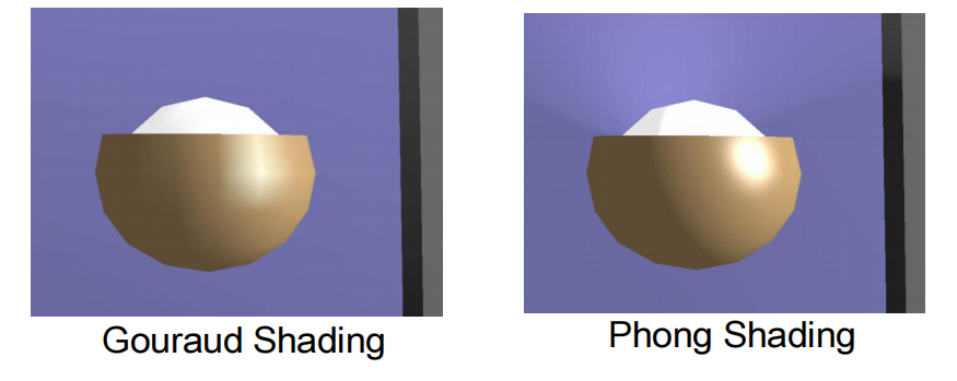
- Differences
- Highlights are produced more faithfully with Phong shading
- Gouraud shading produces only “linear interpolation” of colors
- Gouraud shading may even miss the highlight
- OpenGL does not support Phong Shading
- But can be done by reprogramming the rendering pipeline using shaders
VIII. Modern OpenGL (Intro)
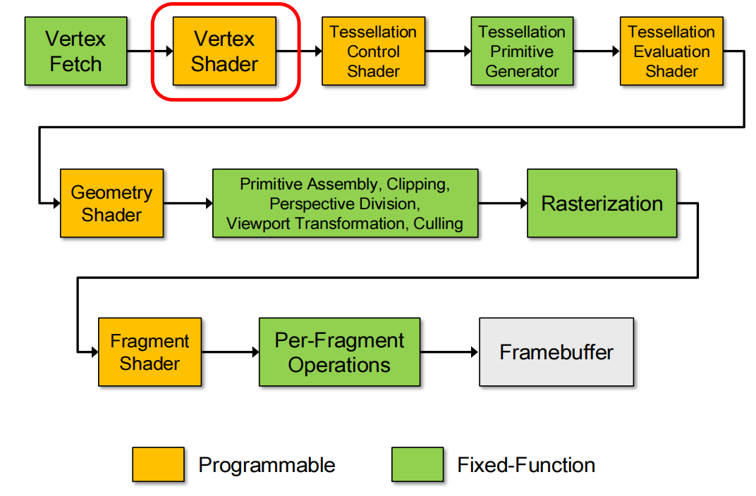
Example OpenGL Programs: The Modern Way
New Lib
GLEW- The OpenGL Extension Wrangler Library
- a cross-platform open-source C/C++ extension loading library
- provides efficient run-time mechanisms for determining which OpenGL extensions are supported on the target platform
- Automatically initializes the entry points of new OpenGL functions
GLM- OpenGL Mathematics
Examples
注意:由于课程上给出的示例代码过长,这里只总结一些重要部分,不展示示例代码。OpenGL 的相关教程网上不会缺,可以自行获取。
IX. Shading Language
This section is all about coding.
Some basis(Data Type, Data Structure, etc.) is ignored.
Storage Quantifiers
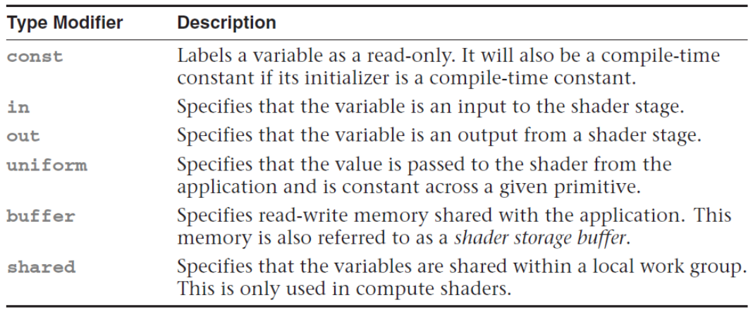
Function Parameter Qualifiers

- GLSL has no concepts of pointer or reference
- Functions are called by value-return
Vertex and Fragment Built-in Variables
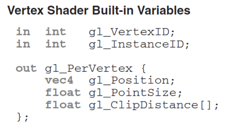 |
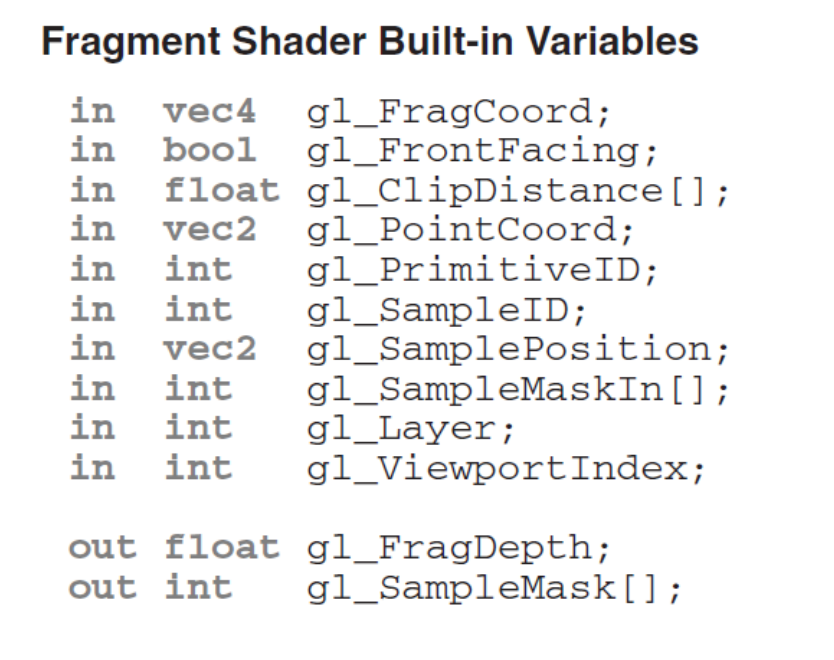 |
-
gl_FragCoordcontains window relative coordinates $(x, y, z, 1/w)$- $z$ is the depth value (after depth range scaling)
- $w$ is $–z_e$ where $z_e$ is the $z$-coordinate of the fragment in the eye space
-
If
gl_FragDepthis not written to,gl_FragCoord.zis used as fragment’s depth -
A fragment’s 2D position is the window-relative coordinates of the fragment’s center
- By default, for the bottom-left-most pixel in the window
gl_FragCoord.x == 0.5gl_FragCoord.y == 0.5
- By default, for the bottom-left-most pixel in the window
Modern OpenGL uses
.vertand.fragto describe the vertex and fragment rendering.
1 | // A simple pseudo-code |
X. Texture Mapping & Applications
Surface Parameterization
- Defines a mapping between the 3D surfaces and the 2D texture map
- Defines the mapping $(x_w, y_w, z_w) \leftrightarrow (s,t)$
- $(x_w, y_w, z_w)$ is the 3D coordinates of surface point
- $(s, t )$ is the 2D texture coordinates (limited to $[0,1]^2$)
- Defines which “texel” maps to each surface point
- Defines the mapping $(x_w, y_w, z_w) \leftrightarrow (s,t)$
- Difficulty
- Non-trivial surface topology causes severe distortion of textures (有些不正常的表面拓扑后会产生纹理混乱)
XI. FBO & Shadow Mapping
Framebuffer Objects(FBO)
Multi-Pass Rendering
Def. Render 3D scene multiple times (passes), and “combine” the multiple rendered images to synthesize final frame
- Allows creation of non-displayable framebuffers
- OpenGL can redirect rendering output to FBO
- Each FBO contains a collection of rendering destinations
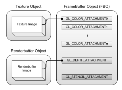
- Two types of framebuffer-attachable images
- Texture images
- Render to texture
- Renderbuffer images
- Offscreen rendering
- Texture images
- Many color attachment points allow multiple render targets (MRT)
- Can query the maximum number of color attachment points with
GL_MAX_COLOR_ATTACHMENTS(usually 8)
- Can query the maximum number of color attachment points with
Example
1 | // cpp file |
1 | // often in other functions |
1 | // DRAW FINAL FRAME |
Shadow Mapping
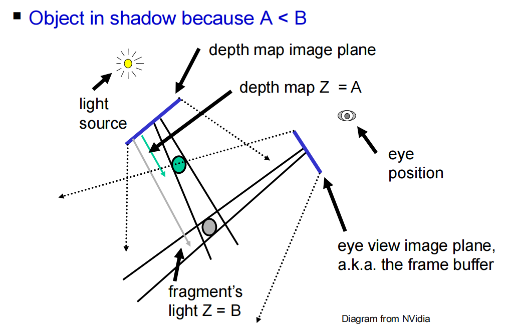 |
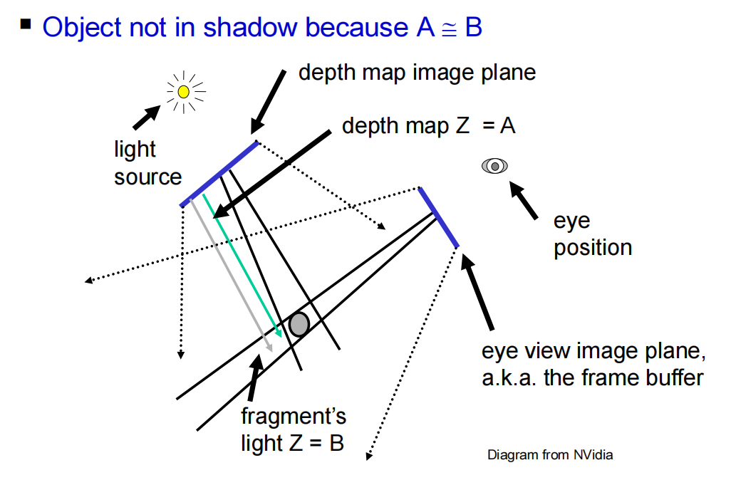 |
Algorithm Overview
- Render the scene using the light source as viewpoint
- Save the depth buffer (a.k.a. shadow map)
- Clear the framebuffer
- Render the scene from camera’s viewpoint
- For each fragment, transform it to the “light space” and compare its “light space” $z$ value with the corresponding $z$ value in the shadow map
- If “light space” z value is larger, the fragment is in shadow and it is lit with only ambient light
- Otherwise, the fragment is not in shadow and is fully lit
- For each fragment, transform it to the “light space” and compare its “light space” $z$ value with the corresponding $z$ value in the shadow map
Shadow Map Coordinates
- Any 3D point in the view frustum(视图) of the light source must be transformed to the shadow map coordinates $[s, t, p]$ where $s$, $t$, $p$ are in the range $[0,1]$
- Given a 3D point $p_M$ in modeling coordinates, its shadow map coordinates $p_L$ is
$$
p_L=B \cdot P_L \cdot V_L \cdot M \cdot p_M
$$
- $M$ is the modeling matrix
- $V_L$ is the light’s view transformation matrix
- $P_L$ is the light’s projection matrix
- and $B=\left[ \begin{array} \
0.5&0&0&0.5 \
0&0.5&0&0.5 \
0&0&0.5&0.5 \
0&0&0&1 \
\end{array}\right]$
Issues
- shadow acnes(失真)
- Sol 1: Subtract a tolerance value from
ShadowCoord.zin the fragment shader before the depth comparison - Sol 2: “Offset” the scene backwards when generating the shadow map from the light source
- Use OpenGL function
glPolygonOffset()
- Use OpenGL function
- Sol 1: Subtract a tolerance value from
- Obvious jaggies(锯齿)
- Percentage Closer Filtering (PCF)
1 | // before using PCF |
1 | // after using PCF |
XII. Image Processing
XIII. Ray Tracing
Basic Ray Casting
1 | For every pixel |
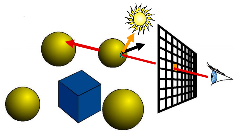
Rasterization vs. Ray Casting
- Rasterization
- Given a primitive in 3D space, determine which pixels are covered by the primitive
- Ray Casting
- At each pixel, determine which primitive covers it
Ray Tracing
- From the closest intersection point, secondary rays are shot out
- Reflection ray
- Refraction ray
- Shadow rays
Whitted-style(Recursive) Ray Tracing
$$
\begin{align}
&\textbf{I}= \textbf{I}{\text{local}}+k{\text{rg}} \textbf{I}{\text{reflected}}+k{\text{tg}} \textbf{I}{\text{transmitted}} \
\text{where }&\textbf{I}{\text{local}}= \textbf{I}{a}k_a+ \color{red}k{\text{shadow}}\color{black}\textbf{I}_{\text{source}}\left[ k_d(\textbf{N} \cdot \textbf{L}) + k_r (\textbf{R} \cdot \textbf{V})^n + k_t (\textbf{T} \cdot \textbf{V})^m \right]
\end{align}
$$
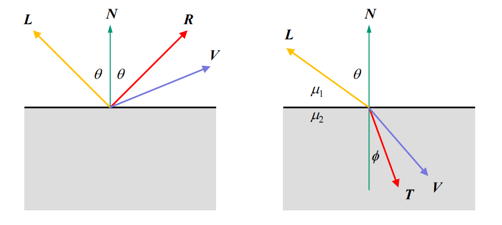
- So if the material is opaque, the $k_t (\textbf{T} \cdot \textbf{V})^m$ can be omitted.
- Also consider Shadow Rays.
Scene Description
- Camera view & image resolution
- Camera position and orientation in world coordinate frame
- Similar to
gluLookAt()
- Similar to
- Field of view
- Similar to
gluPerspective(), but no need near & far plane
- Similar to
- Image resolution
- Number of pixels in each dimension
- Camera position and orientation in world coordinate frame
- Each point light source
- Position
- Brightness and color ($\text{I}_{source}$)
- A global ambient ($\text{I}_{a}$)
- Spotlight is also possible
- Each object surface material
- $k$ (each is a RGB vector)
- $n$, $m$
- Refractive index $\mu$ if $k_{tg} \not= 0$ or $k_{t} \not= 0$
- Objects
- Implicit representations (e.g. plane, sphere, quadrics)
- Polygon
- Parametric (e.g. bicubic Bezier patches)
- Volumetric
Q: When to stop recursion?
- When the surface is totally diffuse (and opaque)
- When reflected/refracted ray hits nothing
- When maximum recursion depth is reached
- When the contribution of the reflected/refracted ray to the color at the top level is too small
- $(k_{rg1} | k_{tg1}) \times … \times (k_{rg(n−1)} | k_{tg(n−1)}) < \text{threshold}$
Appendices (Reference)
If you want to search the reference pages of OpenGL Programming on C++ , or use real-time 3D rendering in other field using OpenGL API, please refer to the OpenGL® 4.5 Reference Pages .
If you are just interesting in shader rendering (like only do fragment shaders), you can go to shadertoy to take a look at others’ work or create your own.
One of the contributor of “shadertoy”, Inigo Quilez, has published a tutorial of the skills of shadertoy, and you can learn it here → https://iquilezles.org/articles/