CS305 计算机网络
Chapter 1: Introduction
1.1 what is the Internet?
1.2 network edge
- end systems, access networks, links
1.3 network core
- packet switching, circuit switching, network, structure
1.4 delay, loss, throughput in networks
1.5 protocol layers, service models
1.6 networks under attack: security
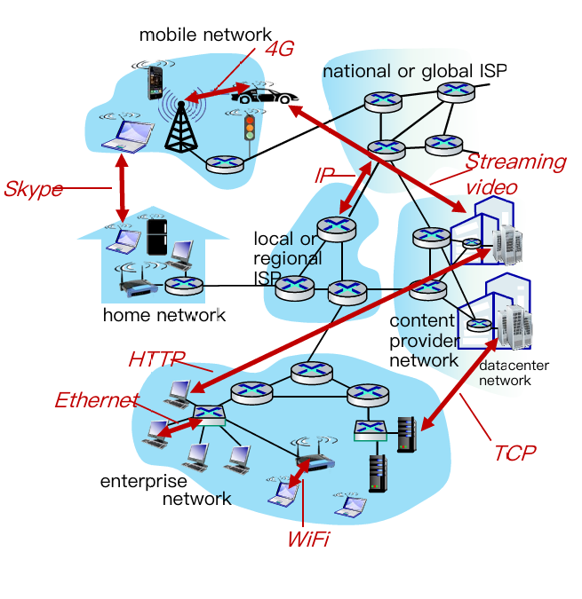
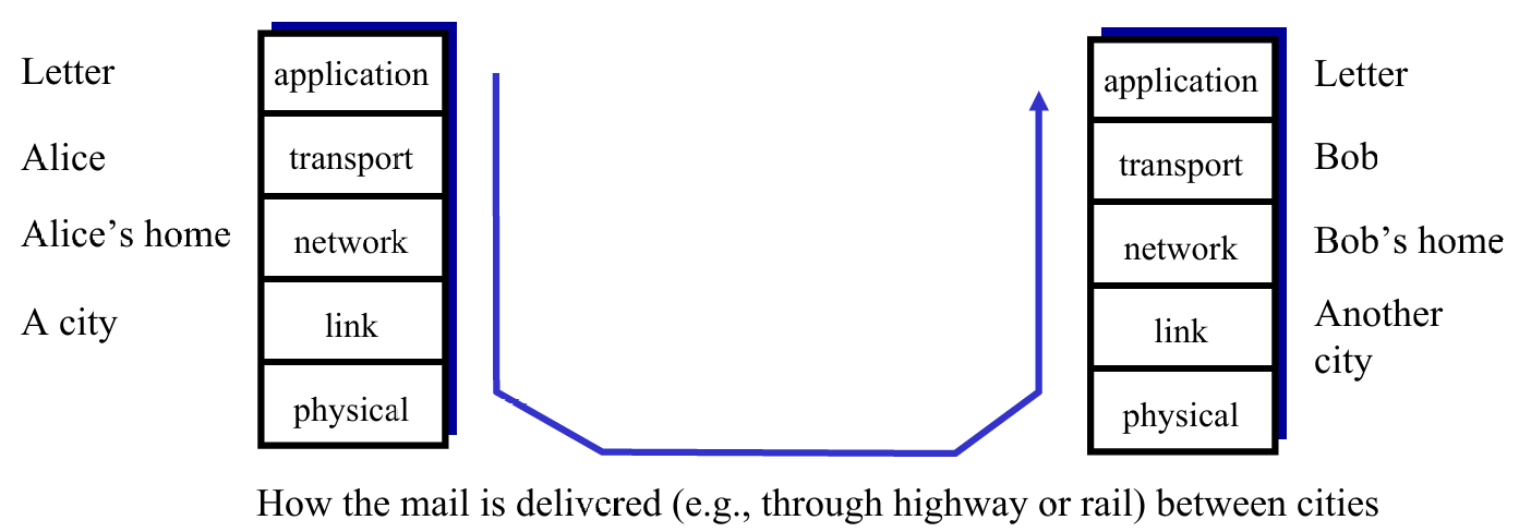
Learning top-down, we have 5 layer about computer network
- Application: supporting network applications
- IMAP, SMTP, HTTP
- Transport: process-process data transfer
- TCP, UDP
- Network: routing of datagrams from source to destination
- IP, routing protocols
- Link: data transfer between neighboring network elements
- Ethernet, 802.11 (WiFi), P2P
- Physical: bits “on the wire”
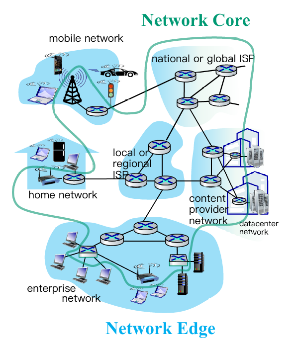
1.1. Structure of Internet
 |
 |
1.2. Network edge
- end systems (hosts):
- run application programs
- e.g. Web, email
- at “edge of network”
- client/server model
- client host requests, receives service from always-on server
- e.g., Web browser/server; email client/server
- peer-peer model:
- minimal (or no) use of dedicated servers
- e.g. Skype, BitTorrent
Hosts: sends packets of data
Host sending function:
- takes application message
- breaks into smaller chunks, known as packets, of length $L$ bits
- transmits packet into access network at transmission rate $R$
- aka link capacity, bandwidth (即链路容量或带宽)
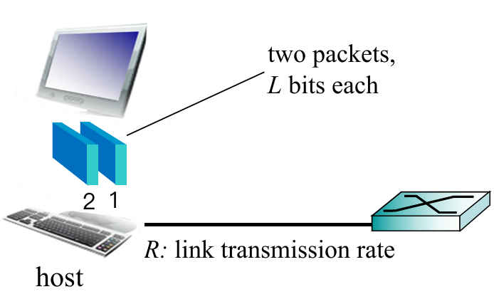
$$
\text{packet transmission delay}=\frac{L\text{(bits)}}{R\text{(bits/sec)}}
$$
Plus: Access Networks(接入网)
Def. The network that physically connects an end system to the first router (edge router) on a path from the end system to any other distant end system.
Different kinds of access networks:
- Cable network
- Digital subscriber line (DSL)
- Home network
- Wireless access network
- Enterprise access network
Cable network
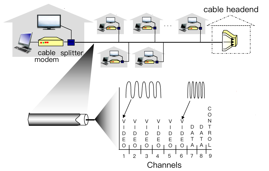
- Cable Internet access makes use of the cable television company’s existing cable television infrastructure.
- Shared broadcast medium
- Shared downstream and upstream
- Distributed multiple access control: avoid collision (分频段控制)
- Applying Frequency division multiplexing (频分复用)
- Hybrid fiber coax (HFC): fiber + coaxial cable (光纤+同轴电缆)
- asymmetric: up to 30 Mbps downstream transmission rate(下行传输效率), 2 Mbps upstream transmission rate
- network of cable, fiber attaches homes to ISP router
- homes share access network to cable headend(多家庭网络接入同一电缆头部)
DSL(digital subscriber line)
- Digital subscriber line (DSL) makes use of the its wired local phone(有线本地电话) access of local telephone company (telco).
- Use existing telephone line to central office DSLAM
- data over DSL phone line goes to Internet
- voice over DSL phone line goes to telephone net
- < 2.5 Mbps upstream transmission rate (typically < 1 Mbps)
- < 24 Mbps downstream transmission rate (typically < 10 Mbps)
Wireless Access Network
- Shared wireless access network connects end systems to router
- via base station aka “access point”
- Wireless LANs(WLAN):
- within building (100 ft)
- 802.11b/g/n/ac (WiFi): 11, 54, 800, 1733 Mbps transmission rate
- Wide-area wireless access
- provide by telco (cellular) operator
- 10 Mbps, 100Mbps, 10Gbps
- 3G, 4G, 5G
补充:信号传输物理介质
- 单位:bit
- 有向介质
- 固体介质如铜,光纤和同轴缆线
- 无向介质
- 无线电
1.3. Network Core(网络核心)
Def. The mesh(链路网格) of packet switches and links that interconnects the Internet’s end systems.
Packet switching vs. Circuit switching
Packet Switching
Basic thought: Hosts break long messages into packets and each packet is forwarded independently.
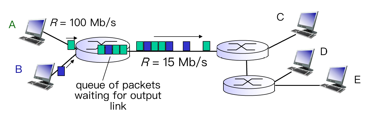
- store-and-forward
- each packet is transmitted at full link capacity
- not reserved → queueing delay and packet loss
- queuing delay: packets will queue, wait to be transmitted on link
- packet loss(丢包): packets can be dropped (lost) if memory (buffer) fills up
Make it clear: what’s routing ? what’s forwarding ?
Routing is global actions: determine source-destination paths taken by packets, and need routing algorithm
Forwarding is local actions (inside 1 router): move arriving packets from router’s input link to appropriate router output link
Circuit Switching: FDM vs. TDM
Basic thought: Determine path before the message being transmitted (called).
-
Advantage: Guaranteed constant rate
-
Reserved (dedicated resources): buffer, link
-
Limitation: Circuit idle(空闲)if not used by call (no sharing)
-
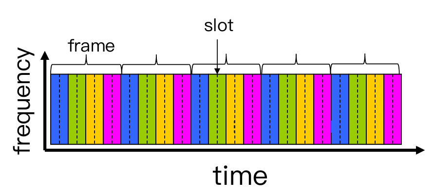
About FDM(频分复用) and TDM(时分复用)
- FDM divides frequencies into (narrow) frequency bands → bandwidth
- transmit at max rate of that narrow band
- TDM divides time into slots
- at maximum rate of (wider) frequency band, but only during its time slot(s)
- have T virtual links in each frame (graph below)
- FDM divides frequencies into (narrow) frequency bands → bandwidth
An example to calculate delay in Circuit Switching:

----- COMPARISON -----
| Packet Switching | Circuit Switching |
|---|---|
| not reserved | reserved (dedicated resources): buffer, link, transmission rate |
| packet forwarded independently(每步独立) | establish an end-to-end link |
| at full link capacity | a fraction of each link’s capacity |
| queuing delay | guaranteed constant rate |
| packet loss | circuit segment idle |
Therefore, Packet Switching is more used in network(more users but have low prob to online at the same time), Circuit Switching is more used in telephone call(assuring rate and connection).
Network Structure

- Different ISPs from different business
- Internet exchange point(IXP) as a connection between ISPs, or direct linking by peering links
- Regional network may arise to connect access nets to ISPs
- Content provider networks(e.g. Google, Microsoft) may run their own network, to bring services, content close to end users.
1.4. Performance Metric
- Delay
- Nodal delay & end-to-end delay
- Packet Loss
- Throughput
- the amount of data per second that can be transferred between end systems
Recall: Packet Switching would make packets queuing at each router(delay), if a router is full, the new packet would be dropped(loss).
Delay: Nodal vs. End-to-end
Nodal Delay
$$
d_{\text{nodal}}=d_{\text{proc}}+d_{\text{queue}}+d_{\text{trans}}+d_{\text{prop}}
$$
- $d_{\text{proc}}$ : nodal processing
- check bit errors
- determine output link
- typically < 1 msec
- $d_{\text{queue}}$ :
- time waiting at output link for transmission
- depends on congestion(拥堵) level of router
- $d_{\text{trans}}$ : 传输时延
- $L$: packet length (bits)
- $R$: transmission rate (bps)
- $d_{\text{trans}} = L/R$
- $d_{\text{prop}}$ : 传播时延
- $d$: length of physical link
- $s$: propagation speed in medium (~$2x10^8$ m/sec)
- $d_{\text{prop}} = d/s$
Easy way to understand $d_{\text{trans}}$ and $d_{\text{prop}}$
Assume that a ten-car caravan(packets) is moving through tollbooth (end/routers). Think of a car as a bit data.
Suppose that the Tollbooth takes 12 sec to service one car (transmission time) and cars runs at a speed of 100 km/hr (propagation speed).
Q: How long does it take the last car to arrive at the 2nd tollbooth?Now the time to “push” entire caravan through tollbooth onto highway = 12 * 10 = 120 sec, known as Transmission Delay;
The time for last car to propagate from 1st to 2nd tollbooth: 100km / (100km/hr) = 1 hr, known as Propagation Delay.
A: 62 mins
- Special: Queuing Delay – Vary from packet to packet
- When characterizing queuing delay, statistical measures:
- average queuing delay
- variance of queuing delay
- the probability that the queuing delay exceeds some specified value
- Use Traffic intensity $=\lambda L / R$ to measure avg queuing delay.
- $\lambda$ : average packet arrival rate (packets per sec)
- $\lambda L / R \to 0$: avg. queueing delay small
- $\lambda L / R \to 1$: avg. queueing delay $\to \infty$ (queuing theory)
- $\lambda L / R \gt 1$: more “work” arriving than can be serviced, average delay infinite!
- When characterizing queuing delay, statistical measures:
End-to-end Delay
$$
d_{\text{end-end}}=N(d_{\text{proc}}+d_{\text{trans}}+d_{\text{prop}})
$$
What do "real" Internet delay & loss look like?
Refer to Lab 1
Throughput(吞吐量)
Def. rate (bits/time unit) at which bits transferred between sender/receiver.
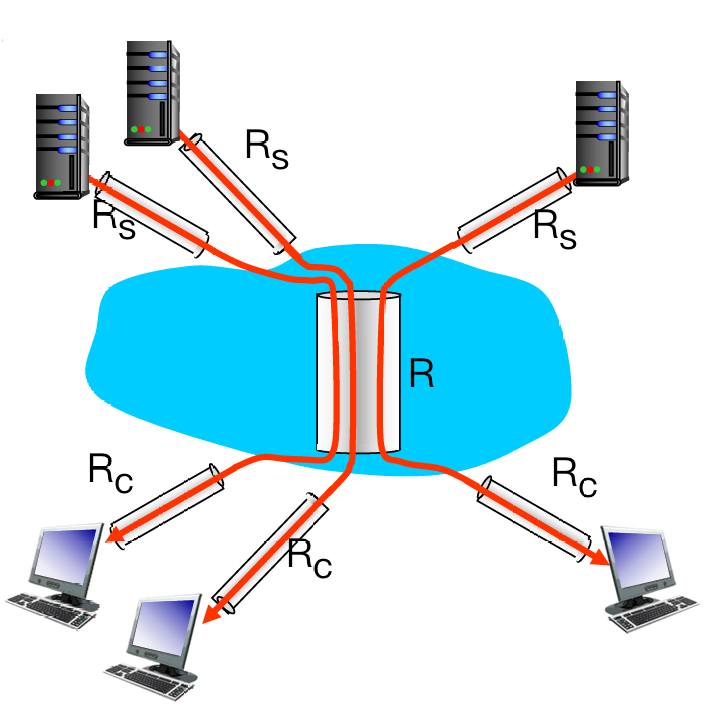
Throughput is decided by the pipe with minimum fluid-carry-rate.
- More complex condition: 10 connections (fairly) share backbone bottleneck link R bits/sec
- Per-connection end-end throughput: $\min{ {R_c, R_s, R/10} }$
- In practice: $R_c$ or $R_s$ is often bottleneck
1.5. Protocol layers & Service models
Q: Why layering?
To deal with complex systems:
- Explicit structure allows identification, relationship of complex system’s pieces
- modularization eases maintenance, updating of system
Q: Any drawbacks?
- One layer may duplicate lower layer functionality
- Functionality at one layer may need information that is present only in another layer
- An easy model to describe how networks layering:
- Layers: Each layer provide services to the layer above
- via its own internal-layer actions
- relying on services provided by layer below
Encapsulation
- Used to keep content of data safe and assure the layer below to acquire enough info to transmit.

1.6. Security
Attack Type
- Malware(恶意软件) into hosts via Internet
- virus
- worm
- Attack server: Denial of Service(DoS), make resources(server, bandwidth) unavailable to legitimate(合法的) traffic by overwhelming resource with bogus(伪造的) traffic.
- aka. 更改 domain 地址
- Sniff packets(拆包,拦截):
- broadcast media
- read all packets passing by
- Use fake addresses:
- send packet with false source address
Defense Lines
- authentication
- confidentiality(密保): via encryption
- integrity checks(多重检测)
- access restrictions
- firewalls:
- off-by-default: filter packets
- detecting / reacting to DoS attacks
Chapter 2: Application Layer
2.1 principles of network applications
2.2 Web and HTTP
2.3 Electronic mail
- SMTP, POP3, IMAP
2.4 DNS
2.5 P2P applications
2.6 video streaming and content distribution networks
2.7 socket programming with UDP and TCP
Learning Goals:
有关网络应用协议的概念与实现:包括用户-服务端架构,peer-to-peer 架构和传输层服务模型
学习一些广泛使用的应用层协议:如HTTP,POP3,DNS等
学习如何搭建简单网络应用:assignment 1 相关,用 python 建立用户-服务端之间的相互通信
2.1. Principles of network applications
- Consider building a network application :
- Q1: Which architecture? client-server or peer-to-peer?
- Q2: Which transport layer protocol to choose? TCP? UDP?
- Q3: Which protocol to follow? HTTP for Web? SMTP for email? Customized?
Architecture of network
Client-Server Architecture
| Server | Client |
|---|---|
| always-on host | communicate with server(can shutdown) |
| permanent(fixed, well-known) IP address | may have dynamic IP addresses |
| data centers for scaling | no direct communication with each other |
P2P Architecture
- no always-in server, directly communicate
- peers request service from other peers, provide service in return to otehr peers
- self scalability: new peers bring new service capacity and new service demands
Hybrid arch: client-server + P2P
Transport layer protocol
Q: How do apps (at end systems) exchange messages? (E.g. how does a browser exchange message with a server?)
A: Split to 2 questions:
- Who send/recv msg to/from network? Process(进程)
- Where does process send/recv msg to/from? Sockets(套接字)
Comparison:
-
- Processes within same host communicate using inter-process communication (defined by OS)
- Processes in different hosts communicate by exchanging messages across the computer network
-
- client process: process that initiates communication (发送方轮询)
- server process: process that waits to be contacted (接收方阻塞)
- (2) is compatible in :
- Client-server architecture
- P2P architectures having client processes & server processes
Interface between Process and Computer Networks: Sockets
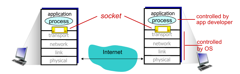
-
Process sends/receives messages to/from the network through socket
- sending process shoves(推送) message “out door”
- sending process relies on transport infrastructure (on other side of door) to deliver message to socket at receiving process
-
To receive messages, sockets must be identified by
- The address of the host: IP address
- An identifier that specifies the receiving process/socket: port numbers (标识进程)
- Some default port number:
- HTTP server: 80
- HTTPS server: 433
- mail server: 25
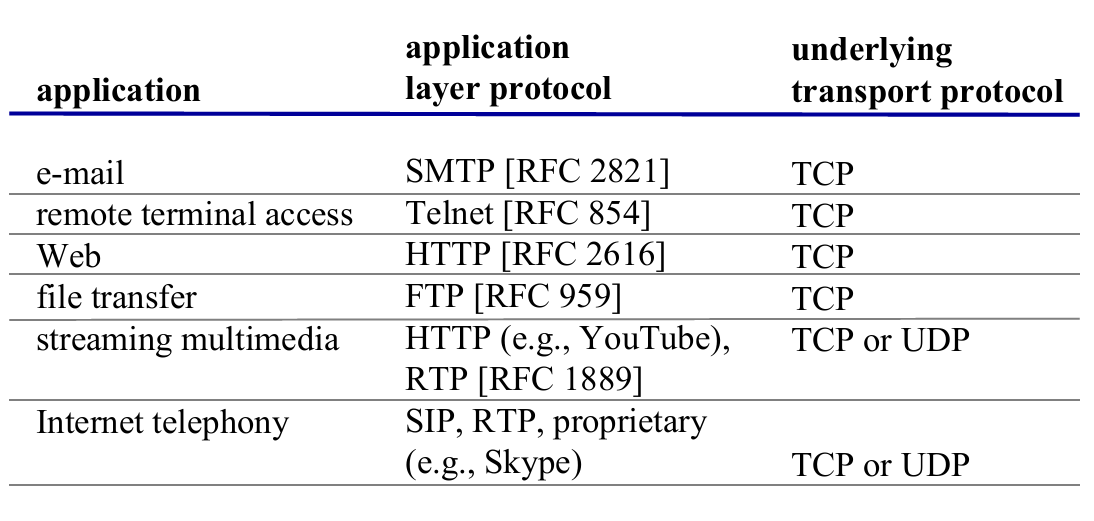
Q: How to choose transport service?
A: choose one of the available transport-layer protocols (e.g., UDP, TCP)
- Measurements for transport service choosing:
- Throughput
- Timing
- Security

- 以上是部分应用的需求,下面我们可以看到这些应用选择了哪项传输服务。
Brief looking on transport protocols
| TCP Service | UDP Service |
|---|---|
| connection-oriented: setup required between client and server processes (TCP connection/full-duplex) | connectionless |
| reliable transport between sending and receiving process | unreliable data transfer between sending and receiving process |
| congestion(拥堵) control: throttle(阻断) sender when network overloaded | - |
| no provide: timing, minimum throughput guarantee, security | no provide: reliability, congestion control, timing, throughput guarantee, security, or connection setup |
注意!TCP 和 UDP 都不直接保证安全性。TCP 保证连接稳定,UDP 保证传输效率。
UDP 适用于时间敏感的通信中。当遇到丢包比延迟要好的情况时,就使用 UDP 传输。
Application-level protocols (Brief)
- App-layer protocol defines
- types of messages exchanged
- e.g., request, response
- message syntax (语法)
- what fields in messages & how fields are delineated
- message semantics (语义)
- meaning of information in fields
- rules for when and how processes send & respond to messages
- types of messages exchanged
应用层协议只是应用的一部分:
以 Web 为例:Web 是一个服务端-客户端应用,允许用户从 Web 服务器获取文档,其组成有
- 一个文档标准格式(HTML)
- Web 浏览器(Browsers)
- Web 服务器
- 应用层协议
2.2. Web and HTTP
- Web page consists of base HTML-file which includes several referenced objects
- each object is addressable by a URL
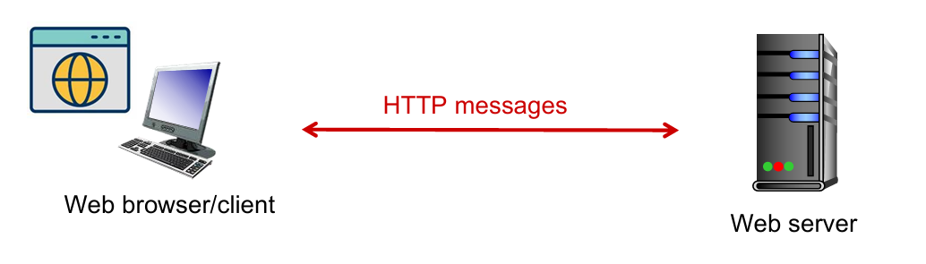
- Web
- client-server architecture
- use HTTP as its application layer protocol
- HTTP (hypertext transfer protocol) defines
- HTTP request: how Web clients request Web pages from Web servers
- HTTP response: how servers transfer Web pages to clients
Client-server architecture: client: browser that requests, receives, (using HTTP protocol) and “displays” Web objects server: Web server sends (using HTTP protocol) objects in response to requests |
 |
HTTP
Outline
- HTTP Overview
- HTTP runs over TCP
- HTTP is stateless
- Persistent and non-persistent connection
- Request and response messages
- Cookies
- Web caching
HTTP overview: TCP
- client initiates TCP connection (creates socket) to server, port 80
- server accepts TCP connection from client
- HTTP messages (application-layer protocol messages) exchanged between browser (HTTP client) and Web server (HTTP server)
- TCP connection closed

HTTP is “stateless” !
- Server maintains no information about past client requests.
- If a client asks for the same object twice, the server resends the object.
Persistent & non-persistent connection
| persistent HTTP | non-persistent HTTP |
|---|---|
| multiple objects can be sent over single TCP connection between client and server | at most one object sent over TCP connection, then connection closed |
| server leaves connection open after sending response; server closes a connection when it isn’t used for a certain time |
OS overhead (TCP buffer, variables) for each TCP connection |
| client sends requests as soon as it encounters a referenced object | browsers often open parallel TCP connections to fetch referenced objects |
Conception. RTT(round-trip-time) is time for a small packet to travel from client to server and back (一个来回)
- For persistent HTTP, time from init TCP conn to, e.g., $n$ times files received is :
$$
\text{Time}=1\text{RTT}+n\times\text{RTT}
$$
- For non-persistent HTTP, is :
$$
\text{Time} = 2\times \text{RTT}
$$
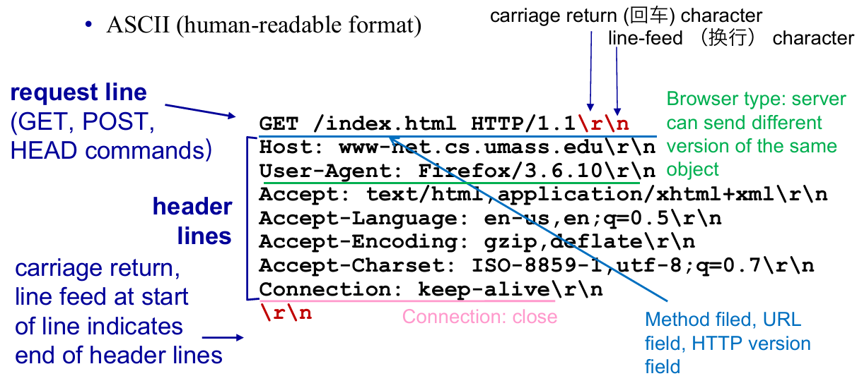
Messages
- HTTP request messages
 |
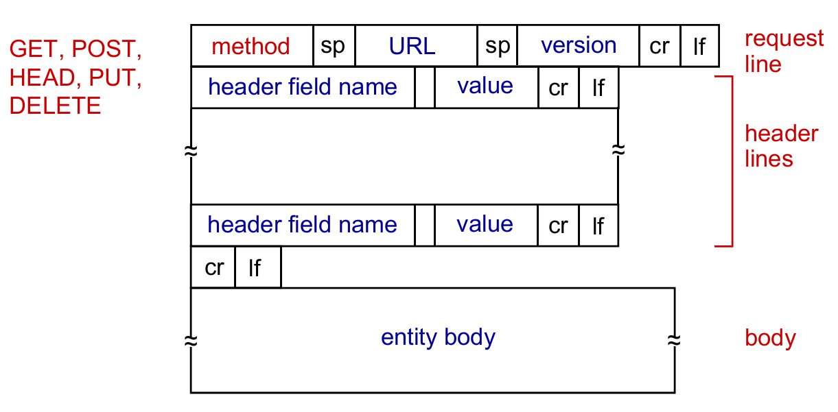 |
| Particular case | General cases |
- HTTP response messages
 |
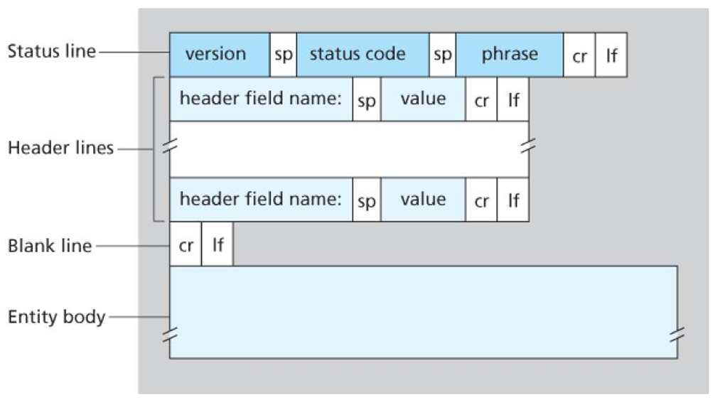 |
| Particular case | General cases |
Status Code
200 OK301 Moved Permanently400 Bad Request404 Not Found505 HTTP Version Not Supported
Cookies
因为 HTTP 是无状态的,但是 Web 应用有保存用户状态的需求,所以需要一个机制识别用户

Cookies 的工作原理

- Cookies are associated with web browser
- E.g. Suppose “Bob” register for Amazon server, then he get a cookie for himself (user-level), but “Susan” have no cookie for Amazon. If she also register(even in same host), the web browser will store a cookie for her.
- Cookies and privacy:
- cookies permit sites to learn a lot about you
- you may supply name and e-mail to sites
Web caches: proxy(代理) server
目的:用户无需访问原始服务器来获取资源

- Cache (Proxy server) acts as both client and server
- server for original requesting client
- client to origin server
- typically cache is installed by ISP (university, company, residential ISP)
- Why Web caching?
- reduce response time for client request (bottleneck bandwidth)
- reduce traffic on an institution’s access link
- Internet dense with caches: enables “poor” content providers to effectively deliver content (so does P2P file sharing)
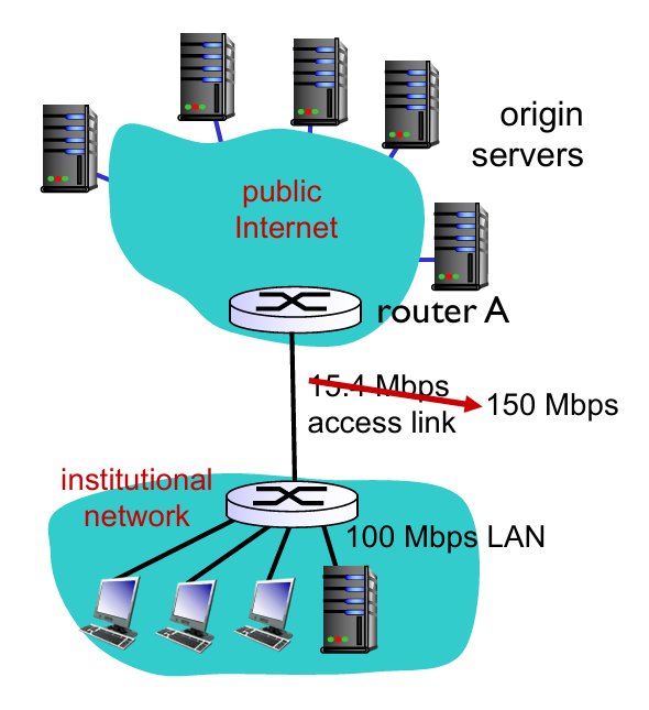
- Assume that
- avg object size: $1M$ bits
- avg request rate from browsers to origin servers: $15$ requests/sec
- avg data rate to all browsers: $15 Mbps$
- RTT from router A to any origin server: 2 sec (Internet delay)
- access link rate: $15.4 Mbps$
- Consequences:
- LAN utilization: $15Mbps/100Mbps=0.15$
- access link utilization: $15/15.4=0.974$
- total delay = Internet delay + access delay + LAN delay = $2sec+\text{minutes} + \text{milliseconds}$
 |
 |
-
Assume that
- access link rate: 150 Mbps (p1)
-
Therefore:
- access link utilization: $15/150=0.1$
- total delay = $2sec + \text{milliseconds} + \text{milliseconds}$
-
Now we have cache server ! (p2)
- suppose cachee hit rate is 0.4 (40% at cache, 60% at origin)
-
Therefore:
- (avg) data rate to browsers over access link $=0.6\times 15 Mbps=9Mbps$
- (avg) access link utilization $=9/15.4=0.58$
- avg delay $=0.6\times \text{(delay from origin servers)}+0.4\times \text{(delay when satisfied at cache)}=0.6\times 2.01 +0.4\times (~msecs) = ~1.2secs$
- Conclusion: faster than with 150 Mbps link and cheaper!
Q: 用户向代理服务器请求内容,如果初始服务器的内容更改,而代理服务器的内容未更新,如何解决?
A: Conditional
GET→GETmethod +If-Modified-Since
- Proxy cache: specify date of cached copy in HTTP request:
If-modified-since: <date> - Server: response contains no object if cached copy is up-to-date:
HTTP/1.0 304 Not ModifiedorHTTP /1.0 200 OKif modified

2.3. Electronic Mail
- Overview
- Main components
- Alice sends an email to Bob
- SMTP
- Mail Message Format
- Mail Access Protocol
- POP3
- IMAP
- HTTP: Web-based Email
Overview
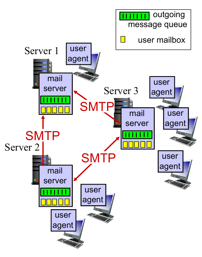
3 major components:
- User agents
- Allow users to read, reply to, forward, save and compose messages
- e.g. Outlook, iPhone mail client
- Mail servers
- Always-on hosts
- User mailbox contains outgoing, incoming messages
- Message queue of outgoing (to be sent) mail messages
- Simple Mail Transfer Protocol (SMTP) between mail servers to send email messages (见上图)
- Both client and server sides of SMTP run on mail server.
- client process: sending mail server
- server process: receiving mail server
- simple mail transfer protocol (SMTP): use TCP
Learning by scenario: Alice sends message to Bob

- Alice uses user agent to compose message “to”
bob@hamburger.edu - Alice’s user agent sends message to her mail server; message placed in message queue
- client side of SMTP opens TCP connection with Bob’s mail server
- SMTP client sends Alice’s message over the TCP connection
- Bob’s mail server places the message in Bob’s mailbox
- Bob invokes his user agent to read message
Simple Mail Transfer Protocol(SMTP)
|
 |
Properties of SMTP :
- SMTP uses persistent connections
- SMTP requires message (header & body) to be in ASCII
- SMTP server uses CRLF(回车换行符) to determine end of message
Comparison with HTTP :
| HTTP | SMTP |
|---|---|
| pull | push //TODO |
| ASCII in header | ASCII in header and body |
| each object encapsulated in its own response message | multiple objects sent in one message |

Q: Why not having mail servers directly on user’s local PC?
A: Mail server manages mailboxes and runs the client and server sides of SMTP. (Bob’s PC have to remain always on in order to receive new mail)

Q: Why not letting Alice send to Bob’s mail server directly?
A: Bob’s mail server may fail; need to repeatedly send the message until success. // TODO
Mail Message Format
How do you write an e-mail …
Header lines, e.g.,
To:,From:,Subject:, etc.
Body, the messages
Mail Access Protocol
Well,
SMTPis used to delivery mail to receiver’s server (a push operation), but how does Bob obtain the mail ?

-
POP3: Post Office Protocol 3: authorization, download
- TCP, port 110(未加密) or 995(加密)
-
IMAP: Internet Mail Access Protocol: more features, including maintain folders, keep user state
-
HTTP: gmail, Hotmail, Yahoo! Mail, etc. [Web-based Email]
-
More about
POP3—— -
Authorization phase
- client commands:
user: declare usernamepass: password
- server responses
+OK-ERR
- client commands:
-
Transaction phase
- client:
list: list message numbersretr: retrieve message by numberdele: deletequit
- client:
-
Update phase (After
Quit, the mail server deletes the messages marked as deletion) -
比较 POP3 和 IMAP
| POP3 | IMAP |
|---|---|
| 邮件下载到本地设备,通常在下载后会从服务器上删除 | 邮件保留在服务器上,用户可以在多个设备上访问同一封邮件 |
| 不支持在多个设备之间同步邮件 | 能够保持所有设备之间的邮件(状态)一致性 |
| 通常不支持文件夹管理 | 支持文件夹管理 |
| 下载后可以在没有互联网的情况下查看邮件 | 设计用于在线访问,包括搜索、标记等操作 |
2.4. Domain Name System(DNS) [重点!]
- DNS Services
- DNS Structure
- Hierarchical structure
- Iterated and recursive query
- DNS protocol
- DNS Records
- Query and reply messages
- Inserting records into DNS
DNS Services
Def. hostname to IP address translation
- Host aliasing
www.ibm.com(alias) is reallyservereast.backup2.ibm.com(canonical 本名)
- load distribution
- replicated Web servers: many IP addresses correspond to one name (多个 IP 共享一个名字)
- rotation distributes the traffic (作用是减轻负担)
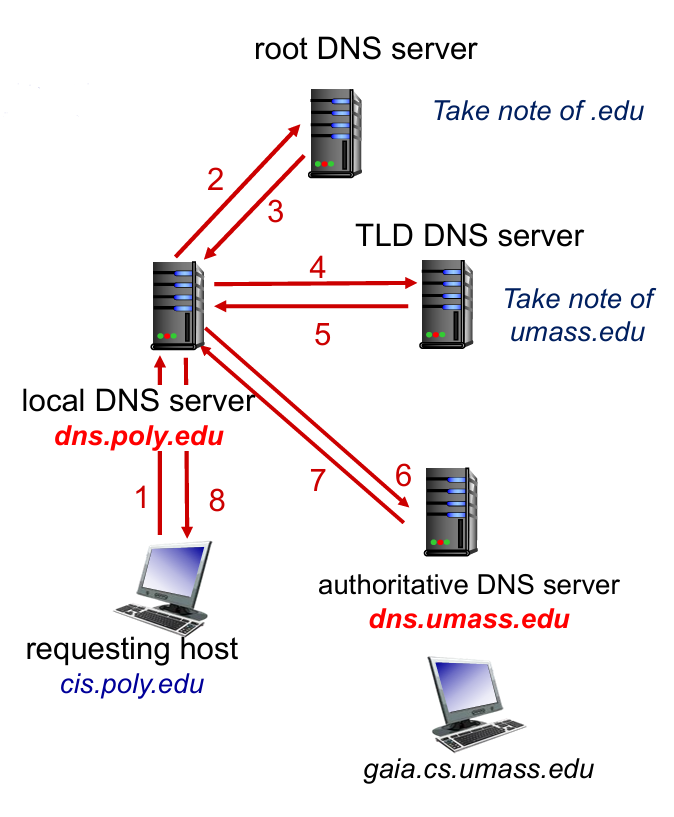
How does APPs invoke DNS Service?
- An application invokes the client side of DNS
- specifying the hostname that needs to be translated
- DNS in the user’s host takes over, sending a query message into the network.
- DNS query and reply messages
- UDP datagrams to port 53. (faster)
- After a delay, ranging from milliseconds to seconds, DNS in the user’s host receives a DNS reply message that provides the desired mapping.
- The mapping (hostname - IP) is then passed to the invoking application.
DNS Structure
为何分层级?
考虑到容错率(单点报错),速度或地区访问差异等。
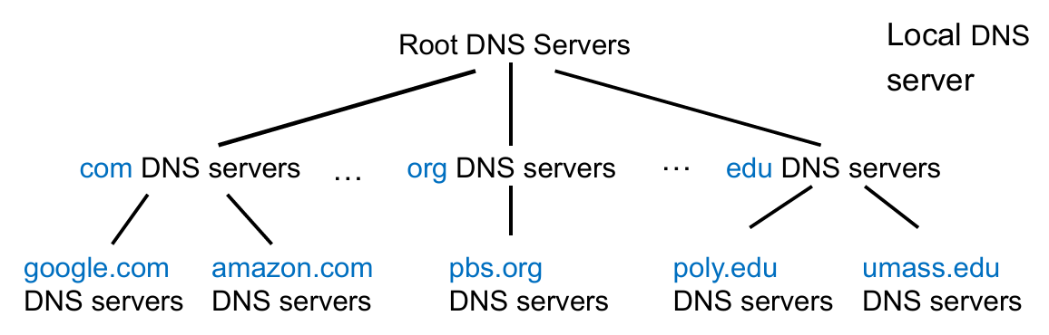
Properties. DNS is a distributed, hierarchical database.
- Root DNS Servers: find IP address of the
.comTLD DNS server (网址越靠后的部分越在顶层)- Provide the IP addresses of the TLD servers
- Top-Level Domain (TLD) DNS: client queries
.comDNS server to getgoogle.comauthoritative DNS server- Top-level domains: com, org, net, edu, aero, jobs, museums;
- Top-level country domains: uk, fr, cn, jp;
- Authoritative DNS servers: client queries
google.comDNS server to get IP address forwww.google.com / scholar.google.com- organization’s own DNS server(s), providing authoritative hostname to IP mappings for organization’s named hosts
- can be maintained by organization or service provider
Local DNS Server
- Does not strictly belong to hierarchy
- Each ISP (residential ISP, company, university) has one
- also called “default name server”
When a host connects to an ISP, the ISP provides the IP addresses of one or more of local DNS servers
When host makes DNS query, query is sent to local DNS server
- acts as proxy, forwards query into hierarchy
- has local cache of recent name-to-address translation pairs (but may be out of date!)
 |
 |
补充:关于如何解决本地 DNS 缓存过期的问题,目前主流的方法是通过设置合理的 TTL (Time to live) 值。时间到了就会重新查询上游 DNS 服务器。
DNS Protocol
Properties. DNS is a distributed database storing resource records (RR).
$$
\text{RR format}=\text{(name, value, type, TTL)}
$$
-
type = A
nameis hostnamevalueis IP address
-
type = NS
nameis domain (e.g.,foo.com)valueis hostname of authoritative server for this domain (e.g.,dns.foo.com)
-
type = CNAME
nameis alias name for some “canonical” (the real) namewww.ibm.comis reallyservereast.backup2.ibm.comvalueis canonical name
-
type = MX
valueis canonical name(真名) of the mailserver withname(alias name)
-
If a DNS server is authoritative for a particular hostname
- the DNS server will contain a Type A record for the hostname
- (Even if the DNS server is not authoritative, it may contain a Type A record in its cache.)
-
If a server is not authoritative for a hostname
- the server will contain a Type NS record for the domain that includes the hostname
- it will also contain a Type A record that provides the IP address of the DNS server in the
valuefield of the NS record.
-
Example: an
.eduTLD server is not authoritative forgaia.cs.umass.edu(umass.edu, dns.umass.edu, NS) // NS record(dns.umass.edu, 128.119.40.111, A) // A record
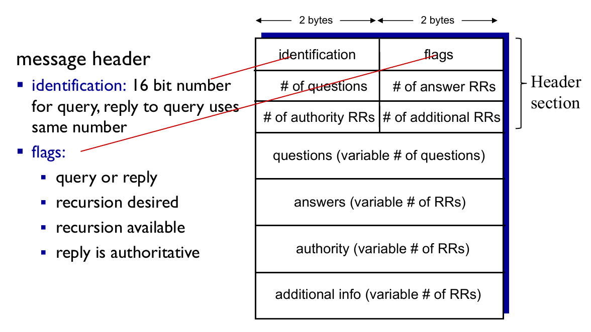
DNS 协议支持查询(Query)和回复(Reply)两种操作,且消息的格式相同。

-
Example: a reply to an MX query
-
Answer section: Type MX
- an RR providing the canonical hostname (at
value) of a mail server.
- an RR providing the canonical hostname (at
-
Additional section: Type A
- the IP address (at
value) for the canonical hostname (atname) of the mail server.
- the IP address (at
Inserting records into DNS
Example
- New startup “Network Utopia”
- Register name
networkuptopia.comat DNS register (e.g., Network Solutions)- provide names, IP addresses of authoritative DNS server (primary and secondary)
- registrar inserts two RRs into
.comTLD server :(networkutopia.com, dns1.networkutopia.com, NS)(dns1.networkutopia.com, 212.212.212.1, A)
- Then users can access by recursive query in the ways shown 👇

Attack DNS (略)
2.5. P2P applications
- Properties
- no always-on server
- arbitrary end systems directly communicate
- peers are intermittently connected and change IP addresses (IP 可变)
- Example
- file distribution (BitTorrent)
- Streaming (KanKan)
- VoIP (Skype)
P2P vs. Client-Server
Question: How much time to distribute file (size F) from one server to N peers?
- Suppose $u_s$ is server upload capacity, $d_i$ is download capacity of peer $i$
- Time to distribute file to all peers $D_{C-S}$ is :
$$
D_{C-S}\ge \max{NF/u_s, F/d_{\text{min}}}
$$
- So the $D$ increases linearly in $N$
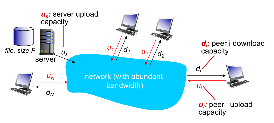
- As each host provide $u_i$ for uploading capacity
- Server must upload at least one copy ($F/u_s$)
- time $D_{P2P}$ is :
$$
D_{P2P}\ge \max{F/d_{min}, F/u_s, NF/(u_s+\sum{u_i})}
$$
P2P file distribution: BitTorrent
How P2P works 👇

- Some points:
- TCP connection with other peers
- Once get entire file, one will leave or remain in BitTorrent
| requesting chunks | sending chunks: tit-for-tat |
|---|---|
| at any time, different peers have different subsets of file chunks | maintain a priority list of top-N peers |
| periodically, asks each “neighbor” for list of chunks | periodically, select one additional peer(“optimistically unchoke”) to start sending chunks, and chokes others |
| request missing chunks, rarest first | sends chunks to those who sending me chunks at highest rate |
通俗解释:请求发包优先找请求得最少的,发包优先发请求最多的。(符合常理)
tit-for-tat
- (1) Alice “optimistically unchokes” Bob
- (2) Alice becomes one of Bob’s top-four providers; Bob reciprocates
- (3) Bob becomes one of Alice’s top-four providers
2.6. video streaming and content distribution networks
- Challenge
- scale —— how to reach ~1B users?
- heterogeneity (异质性) —— different users have different capabilities
- video traffic (视频流量) —— major consumer of Internet bandwidth
- Solution
- distributed, application-level infrastructure
Video has demand of multiple images per sec (e.g. 60 FPS needs 60 img/sec)
Use redundancy within and between images to decrease # bits used to encode image (前后帧图像分块,同色的块不再传输)
A more efficient way below 👇
Streaming multimedia: DASH
- DASH: Dynamic, Adaptive Streaming over HTTP
- Server:
- divides video file into multiple chunks
- each chunk stored, encoded at different rates
- manifest file: provides URLs for different chunks encoded at different rates
- Client:
- periodically measures server-to-client bandwidth
- consulting manifest, requests one chunk at a time
- chooses maximum coding rate sustainable given current bandwidth
- can choose different coding rates at different points in time (depending on available bandwidth at time)
在这里 client 是自由的。何时请求数据块,用哪种编码速率,向哪个地址请求数据块,都由 client 自己决定。
Content Distribution Network(CDN)
Why not using “mega-server” ?
单点错误(容错率低),巨大负载,对远距离用户不友好等
Solution. CDN store/serve multiple copies of videos at multiple geographically distributed sites
- In practice, push CDN servers deep into many access networks; (inside ISPs)
- Or smaller number (10’s) of larger clusters in Internet Exchange Point (IXP); (outside ISPs)
E.g. See how Bob request video by CDN :

用户查找“最近” CDN 服务器的两种策略:地理距离最短或实时计算最短延迟
2.7. Socket programming with UDP and TCP
Goal: learn how to build client/server applications that communicate using sockets.
Socket: door between application process and end-end-transport protocol
Socket programming with UDP
- No “connections”
- Transmitted data may be lost or received out-of-order

- Implementation 【server】
1 | from socket import * |
- Implemetation 【client】
1 | '''Client do not need to specify port-num''' |
Socket programming with TCP
- Client must contact server
- server process must first be running
- server must have created socket (door) that welcomes client’s contact (welcome socket)
- Client contacts server by:
- Creating TCP socket, specifying IP address, port number of server process
- Client TCP establishes connection to server TCP
- when contacted by client, server TCP creates new socket for server process to communicate with that particular client (允许服务端与多个客户连接)
Identifications difference between UDP and TCP socket (对应到同一个套接字所需参数):
UDP = dst.IP + dst.port
TCP = dst.IP + dst.port + src.IP + src.port

- Implementation 【server】
1 | serverPort = 12000 |
- Implementation 【client】
1 | serverName = 'servername' |
Chapter 3: Transport Layer
3.1 transport-layer services
3.2 multiplexing and demultiplexing
3.3 connectionless transport: UDP
3.4 principles of reliable data transfer
3.5 connection-oriented transport: TCP
- segment structure
- reliable data transfer
- flow control
- connection management
3.6 principles of congestion control
3.7 TCP congestion control
3.1. Transport Layer Services
- Transport vs. App
- logical communication between app processes running on different hosts
- Transport protocols run in end systems
- send side: breaks app messages into segments, passes to network layer
- rcv side: reassembles segments into messages, passes to app layer (Recall encapsulations)
- Transport vs. Network
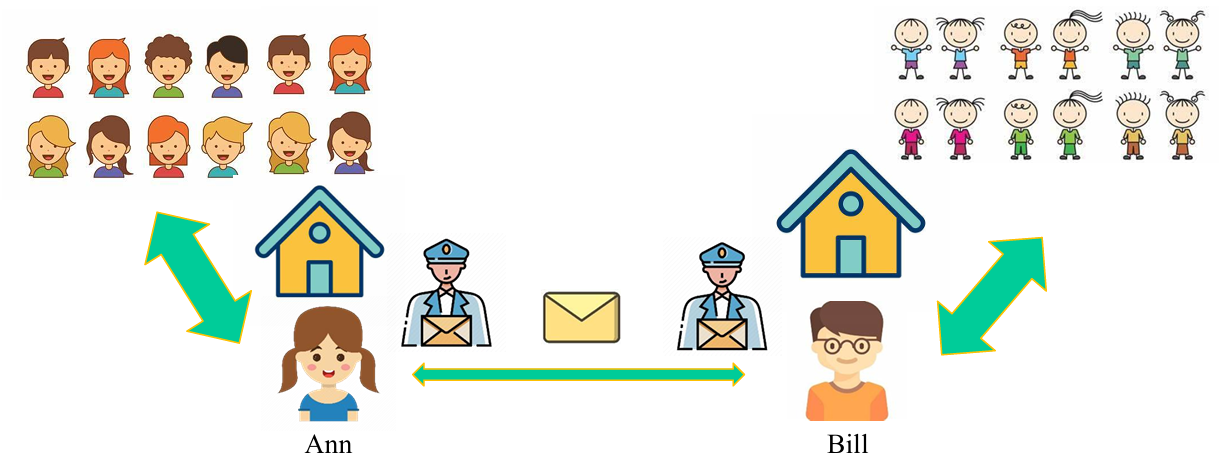
- hosts = houses
- processes = kids
- app messages = letters in envelopes
- transport protocol = Ann and Bill
- network-layer protocol = postal service
大部分传输层的服务包含在网络层中(如确保延迟时间和带宽的服务,因此 UDP 和 TCP 都不包含此服务),但仍有一些是网络层不提供的(如安全保障,rdt等)。
| TCP | UDP |
|---|---|
| reliable, in-order delivery | unreliable, unordered delivery |
| connection setup | no-frills(简洁的) extension |
| congestion control and flow control | process-to-process data delivery and error checking |
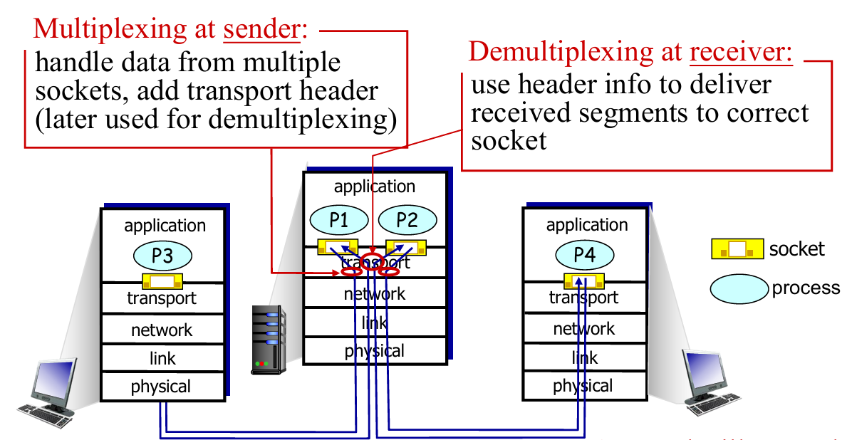
3.2. Multiplexing / Demultiplexing
Def. extending the host-to-host delivery service to a process-to-process delivery service for applications running on the hosts.
在 Ann and Bill 的例子里,这就像每个小朋友(进程)都有对应的名字和 ID,通过对此进行标识,可以让通信双方的 Socket 知道如何进行下一步传输。
- Sending host: Host uses IP addresses & port numbers to direct segment to appropriate socket
- Receiving host:Host receives IP datagrams from network layer
- each datagram has source IP address, destination IP address
- each datagram carries one transport-layer segment
UDP: Connectionless demux

- IP datagrams with same
dst.port#, but different source IP addresses and/or source port numbers will be directed to same socket at destination.
TCP: Connection-oriented demux

图中的 Socket 不再对应于进程,而是对应线程
- Web servers have different sockets for each connecting client
- Both the initial connection-establishment segments and the segments carrying HTTP requests will have destination port 80.
- non-persistent HTTP will have different socket for each request
3.3. Connectionless transport: UDP
- UDP is used in:
- streaming multimedia apps (loss tolerant, rate sensitive)
- DNS
- reliable transfer over UDP: (都是在其他层解决的,所以说 UDP 是不可靠的传输)
- add reliability at application layer
- application-specific error recovery!
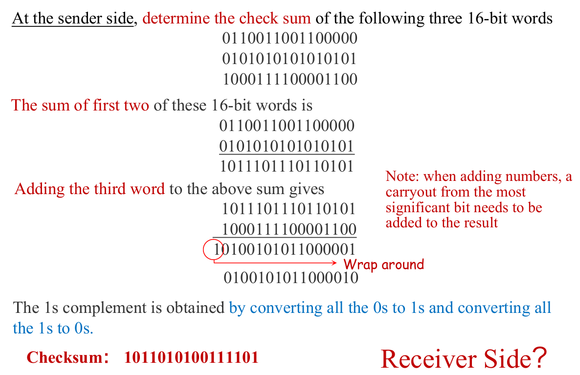
UDP Checksum
Goal: detect “errors” (e.g., flipped bits) in transmitted segment (from source to destination)
- Q: Why UDP using checksum?
- A:
- no guarantee that all the links provide error checking
- bit errors could be introduced when segments are in memory
- Lower cost comparing to checking in app-level.
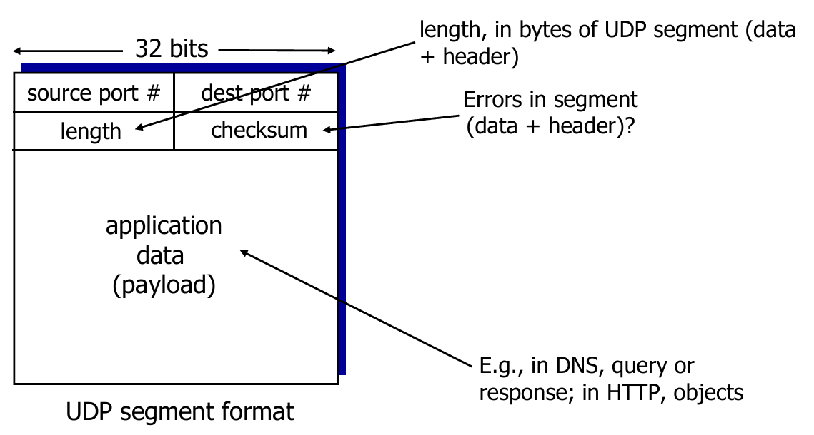
- Sender:
- treat segment contents, including header fields, as sequence of 16-bit integers
- checksum: 1s complement of the sum of segment contents
- sender puts checksum value into UDP checksum field
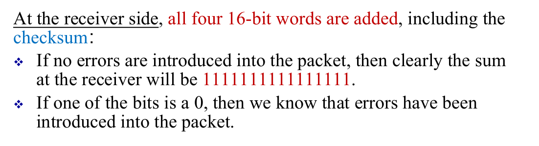
- Receiver:
- check the sum of the segment
- All bits are equal to 1 - no error detected. But maybe errors nonetheless? More later…
- Otherwise: error detected
- check the sum of the segment
Example
一个更简单的证明例子:
设三个加数为
0101,1101,1011$0101+1101=10010 \rightarrow +1011=11101$ ,补位得
1110,取反得0001接收方计算:$0101+1101=10010 \rightarrow +1011=11101 \rightarrow + 0001=11110$,补位得
1111全 1 符合条件,暂时检测不出错误。
3.4. Principles of Reliable Data Transfer (rdt)
Overview
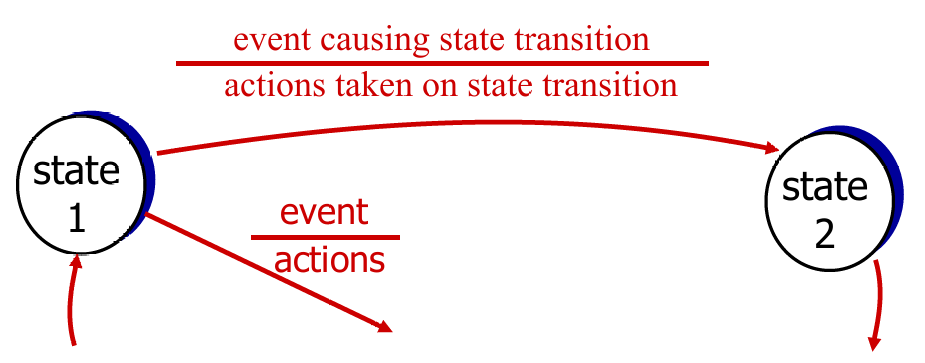
We mainly use FSM to describe rdt clearly. Template as pic above.
- Perfectly reliable channel:
rdt1.0 - Channel with bit error:
- bit error in packet:
rdt 2.0 - bit error in ACK:
2.1 - NAK-free:
2.2
- bit error in packet:
- Lossy channel:
rdt 3.0
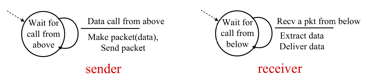
rdt 1.0
- Underlying channel “perfectly reliable”
- no bit error
- no loss of packet
- Therefore, no control for feedback
rdt 2.0
-
Underlying channel may flip bits (0 → 1) in packet
-
Q: how to recover from errors?
- acknowledgements (ACKs): receiver explicitly tells sender that pkt received OK
- negative acknowledgements (NAKs): receiver explicitly tells sender that pkt had errors
- sender retransmits pkt on receipt of NAK
-
New Machanism in
rdt 2.0- Error detection: checksum
- Receiver feedback: control msgs (ACK,NAK)
rcvr->sender - Retransmission
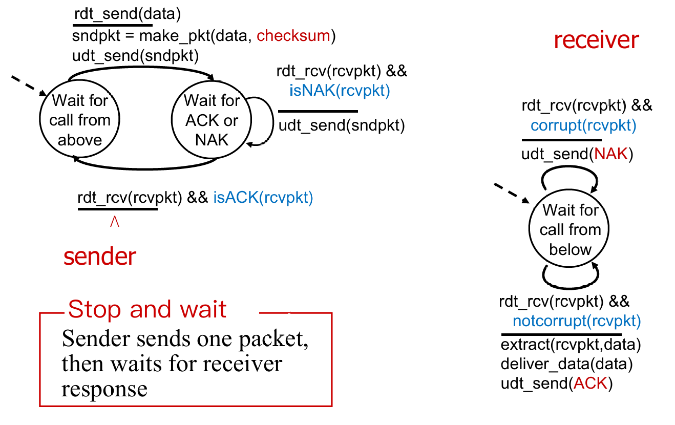
rdt 2.0has a fatal flaw !- What if ACK / NAK packet is corrupted?
- Handling corrupted ACKs or NAKs:
- Op1. Keep asking until get answer ( foolish ! )
- Op2. add enough checksum to recover
- Op3. when garbled ACK or NAK, retransmit (👈seems better, but still some probs)
rdt 2.1

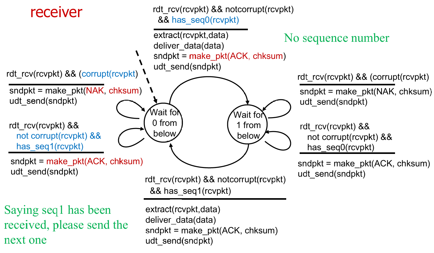
- Recv maintain seq # as Sender do (正常情况下持有相同状态值)
- Sender check if received ACK/NAK corrupted
- Recv check if received packet is duplicate
例:sender 在状态 0,receiver 在状态 0
此时 sender 发送一个 seq0 的包,recv 正常收到,解包并发送 ACK,然后转向状态 1。
但是 sender 没收到 ACK,重发 seq0。recv 则会再发 ACK(根据 FSM),如此到 sender 收到 ACK,然后转向状态 1。然后 sender 发送 seq1 的包。如此循环。
rdt 2.2

- Optimization
- using ACKs only (sends ACK for last pkt received OK)
- must send ACK with seq #
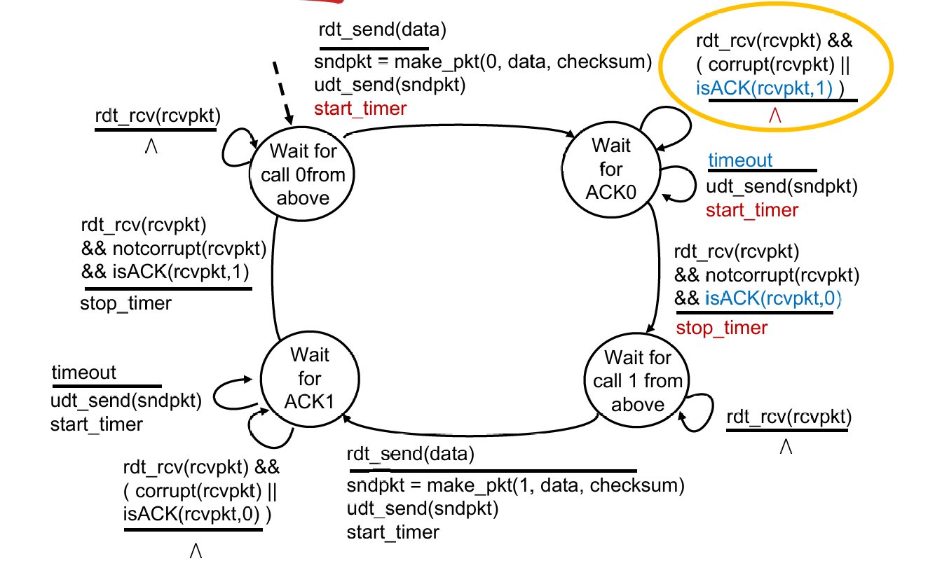
rdt 3.0
-
New Assumption: underlying channel can also lose packets (data, ACKs)
-
Approach: sender waits “reasonable” amount of time for ACK
-
retransmits if no ACK received in this time
-
if pkt (or ACK) just delayed (not lost):
- retransmission will be duplicate, but seq. #’s already handles this
- receiver must specify seq # of pkt being ACKed
-
requires countdown timer
- start timer, timer interrupt, stop timer
-
Sender in
rdt 3.0
Some calculations:
How to calc the utilization of sender ($U_{\text{sender}}$) ? Suppose that $RTT = 30 msec$, $R = 1 Gbps$, $L = 8000 bits$
$U_{\text{sender}}=\frac{L/R}{RTT + L/R}=\frac{.008}{30.008}=0.00027$
Utilization 可以理解成某个终端的有效工作时间占比
Summary
Key techniques
- Checksum (2.0)
- ACK packet (2.0)
- Retransmission (2.0)
- Sequence number (2.1)
- Timeout (3.0)
Pipelined Protocols
- Go-Back-N
- Timer for the oldest unACKed packet
- Cumulative ACK
- Retransmit all packets in the window
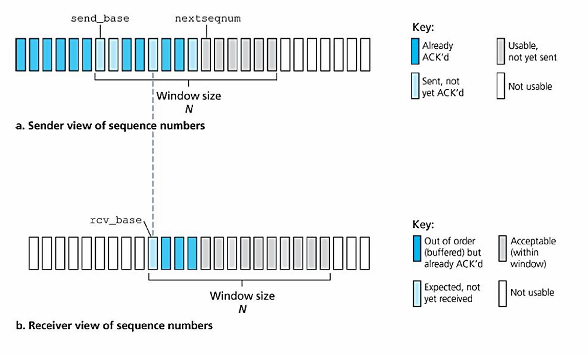
- Selective repeat
- Timer for each packet in window
- Individual ACK for each correctly received packets
- Retransmit only those packets that might be lost or corrupted
Go-Back-N
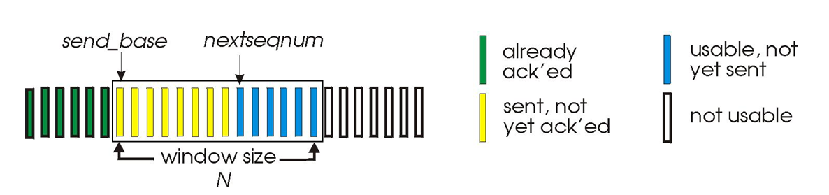
-
$k$-bits seq # in pkt header: range $[0, 2^k -1]$
-
At most $N$ pkts in flight(in the “window”) are allowed
-
Sender: When
rdt_send()is called from above,- window is not full: a packet is sent, variables are updated.
- window is full: simply returns the data back to the upper laye
- A timer for the oldest transmitted but not yet ACKed packet
- timeout occurs: resends all packets in the window;
ACK(n): slide window; restart timer
-
Receiver: Receipt of an ACK.
- Cumulative acknowledgment (ACK)
ACK(n): all packets with a sequence # up to and including $n$ have been correctly received at the receiver- Expect $n$ and receive $n$:
ACK(n) - Expect $n$ and receive others: previous
ACK; discard packet
- Expect $n$ and receive $n$:
Obvious that GBN didn’t have a receiver buffering (discard out-of-order pkt), and generate many dup-ACKs as well !
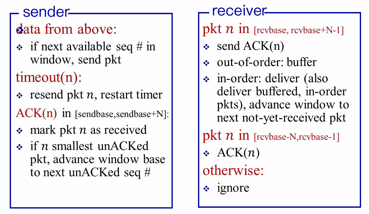
Selective Repeat
- Receiver individually acknowledge all correcly received pkts
- buffers pkts for eventual in-order delivery to upper layer
- Receiver need to keep track of the out-of-packets
- Sender only resends pkts for which ACK not received
- sender maintain timer for each unACKed pkt
Well, it may be hard to understand. So I offer an easy example, with window size is only 4, to show that how would the receiver (more significant) respond to unexpected packet receiving.
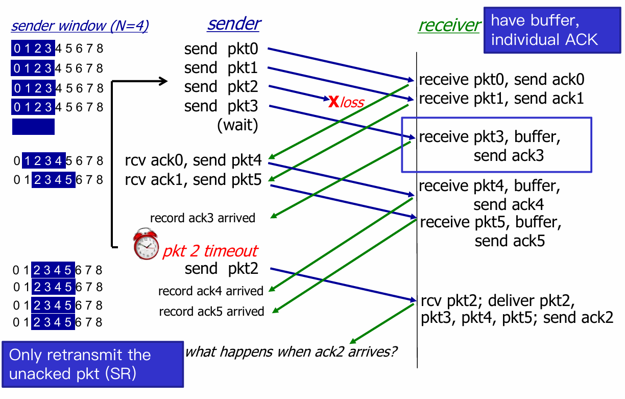
- When
ack2arrives, sender’s window move withpkt6being the sendbase. - But here’s a problem !
- Consider seq # = [0, 3] , and window size N = 3
- Left case is Okay, but consider the wrost case(Right)
 |
 |
- The receiver will recognize the retransmit
pkt0as the latter one, and think that the 2pkt0are both ACKed. - Then receiver send
ACK(0)back to sender.- If sender receive
ACK(0), then everything goes on, but receiver lose the former 3 pkts forever ! - If send doesn’t receive, then sender window sticks to (0, 1, 2), receiver window sticks to (3, 0, 1), which is a deadlock, until sender get
ACK(0).
- If sender receive
- How to deal ? Constraint: Window size N must be less than or equal to half of seq # range.
More detail refer to Lab 8
3.5. Connection-Oriented Transport: TCP
Overview
- point-to-point
- one sender, one receiver
- No buffers or variables are allocated to network elements between hosts
- reliable, in-order byte stream
- no “message boundaries”
- Seq # and ACK # are in unit of byte, rather than pkt
- pipelined
- TCP congestion and flow control set window size
- full duplex data
- bi-directional data flow in same connection
- Maximum Segment Size (MSS)
- connection-oriented
- handshakings init sender and receiver state before data transfer
- flow controlled
- sender will never overwhelm receiver (ensure safety)

- TCP grab chunk of data from the sender buffer
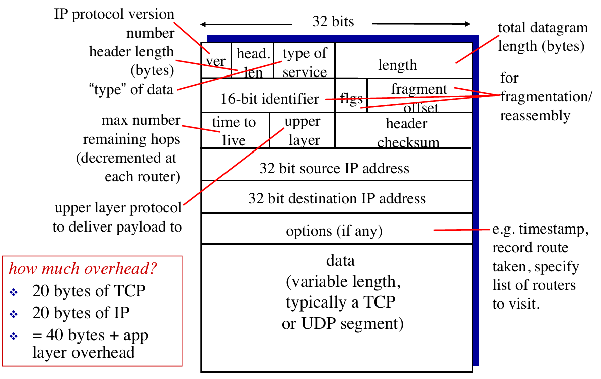
- MSS: maximum segment size, typically 1460 bytes
- MTU: maximum transmission unit (link-layer frame), typically 1500 bytes
- Application data + TCP/IP header ( typically 40 bytes )
- TCP receive a segment at the other end, place it in receiver buffer
- Application reads the stream from the receiver buffer
TCP RDT
Segment Structure

- TCP view data as an untrusted, but ordered, stream of bytes.
- Seq numbers are over the stream of transmitted bytes and not over the series of transmitted segment.
- seq #: byte stream “number” of first byte in the segment’s data
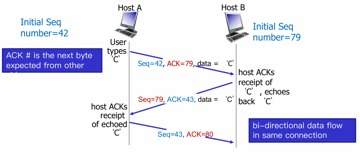
- ACK #: seq # of next byte expected from the other side
- e.g. receiver has received bytes 0 - 535 and 900 - 1000; then, acknowledgement number is 536.
- E.g. Telnet case: User types a
charat host A, and host A sends it to host B
RTT estimation
Recall: Round-trip Time (RTT), the time from sender sending the pkt to sender receiving corresponding ACK.
-
Q: How to set TCP timeout value?
-
longer than RTT 👉 But RTT varies
-
too short 👉 premature timeout, unnecessary retransmission
-
too long 👉 slow reaction to segment loss
-
Q: How to estimate RTT?
-
Sample RTT: measure time from segment transmission until ACK receipt (ignore retransmissions)
-
But it maybe vary. 👉 average several recent measurements, not just current SampleRTT.
$$
\text{EstimatedRTT}=(1-\alpha)\times \text{EstimatedRTT}+\alpha \times \text{SampleRTT}
$$
Typically value $\alpha=0.125$
- Also we need an interval for the toleration of the variability of RTT (typically $\beta=0.25$)
$$
\begin{array}{c}
\text{DevRTT}=(1-\beta)\times\text{DevRTT}+\alpha \times | \text{SampleRTT} - \text{EstimatedRTT} | \
\text{TimeoutInterval}=\text{EstimatedRTT} + 4 \times \text{DevRTT}
\end{array}
$$
Reliable Data Transfer
TCP thinks that IP below itself as unreliable, so it provide reliable data transfer
- Sender Events
- data received from app:
- create segment with seq num (which is byte-stream number of first data byte in segment)
- start timer if not already running
- timeout:
- retransmit the timeout segment
- restart timer
- ack received:
- if ack num from previously unacked segments, update that segments (unACKed 👉 ACKed)
- if there are still unACKed segments, start timer
- data received from app:
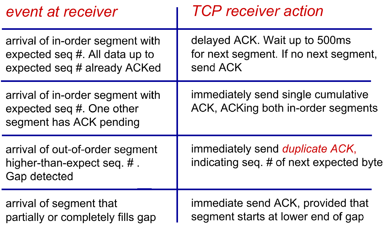
- Receiver Events
Double Timeout
- Each time TCP retransmits, it sets the next timeout interval to twice the previous value
Fast retransmission
…
Flow Control
Def. Receiver controls sender, so sender won’t overflowz receiver’s buffer by transmitting too much, too fast.
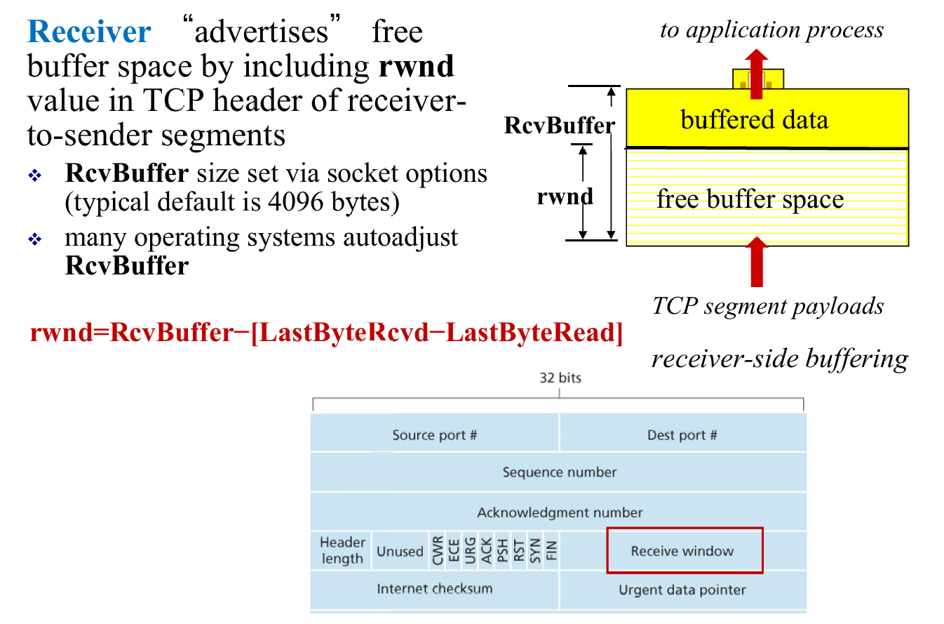
- And sender will try to limit the unACKed data to receiver’s
rwndvalue
Control Managment
- Before data transfer, “Alice” and “Bob” (using TCP) will have a three-way handshakes to guarantee connection.
- Three flags to convey the info about connection:
RST,SYN,FIN

- Once three handshakes finish, the server and client can start data transfer.
- In the future sements,
SYNbit= 0. - After all segments ACKed, the sender closes the connection 👇

3.6. Principles of Congestion Control
Def. Congestion is too many sources sending too much data too fast for network to handle.
Causes / Costs of congestion
(1) 2 senders <(^-^)> 2 receivers; one router with infinite buffer but output link capacity is $R$ ; No retransmission
(2) Consider retransmission
(3) More than one router
Summary
- Cause
- Shared link; limited link capacity
- Sending at a high rate
- Cost of Congestion
- Delay
- Packet lost and retransmission
- Unneeded retransmission: waste
- “upstream” transmission capacity was wasted
- Approaches to Congestion Control
- End-to-end
- TCP segment loss or round-trip segment delay
- TCP decreases its window size accordingly
- Network-assisted congestion control:
- routers provide feedback to the sender and/or receiver
- a single bit indicating congestion at a link; the maximum host sending rate the router can support
- End-to-end
3.7. TCP Congestion Control
- Q1: How does a TCP sender limit the rate at which it sends traffic into its connection?
- Congestion window
- LastByteSend - LastByteAcked $\le$ min {cwnd, rwnd}
- Q2: How does a TCP sender perceive that there is congestion on the path between itself and the destination?
- timeout
- three duplicate ACKs
- Q3: What algorithm should the sender use to change its send rate as a function of perceived end-to-end congestion?
Congestion Control: Details
- Three components:
- Slow start:exponentially increase
- Congestion avoidance: linearly increase
- Fast recovery(as shown below) :

- TCP congestion control: additive increase multiplicative decrease
- additive increase: increase cwnd by 1 MSS every RTT until loss detected
- multiplicative decrease: cut cwnd in half after loss
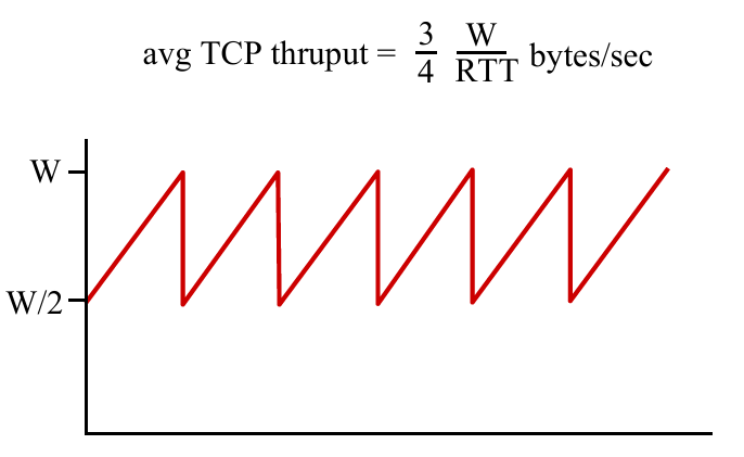
- TCP throughput
- ignore slow start, assume always data to send
- $W$: window size (measured in bytes) where loss occurs
TCP Fairness
Fairness goal: if $K$ TCP sessions share same bottleneck link of bandwidth $R$, each should have average rate of $R/K$
Chapter 4: Network Layer
4.1 Overview of Network layer
- data plane
- control plane
4.2 What’s inside a router
4.3 IP: Internet Protocol
- datagram format
- fragmentation
- IPv4 addressing
- network address translation
- IPv6
4.4 Generalized Forward and SDN
- match
- action
- OpenFlow examples of match-plus-action in action
4.1. Overview of Network Layer
- transport segment from sending to receiving host
- on sending side encapsulates segments into datagrams
- on receiving side, delivers segments to transport layer
- network layer protocols in every host, router
- router examines header fields in all IP datagrams passing through it
Two key network-core functions
- Forwarding: move packets from router’s input to appropriate router output
- Data Plane
- Routing: determine route taken by packets from source to destination
- routing algorithm
- Control Plane
4.2. What’s inside a router

Router Overview
- Input port
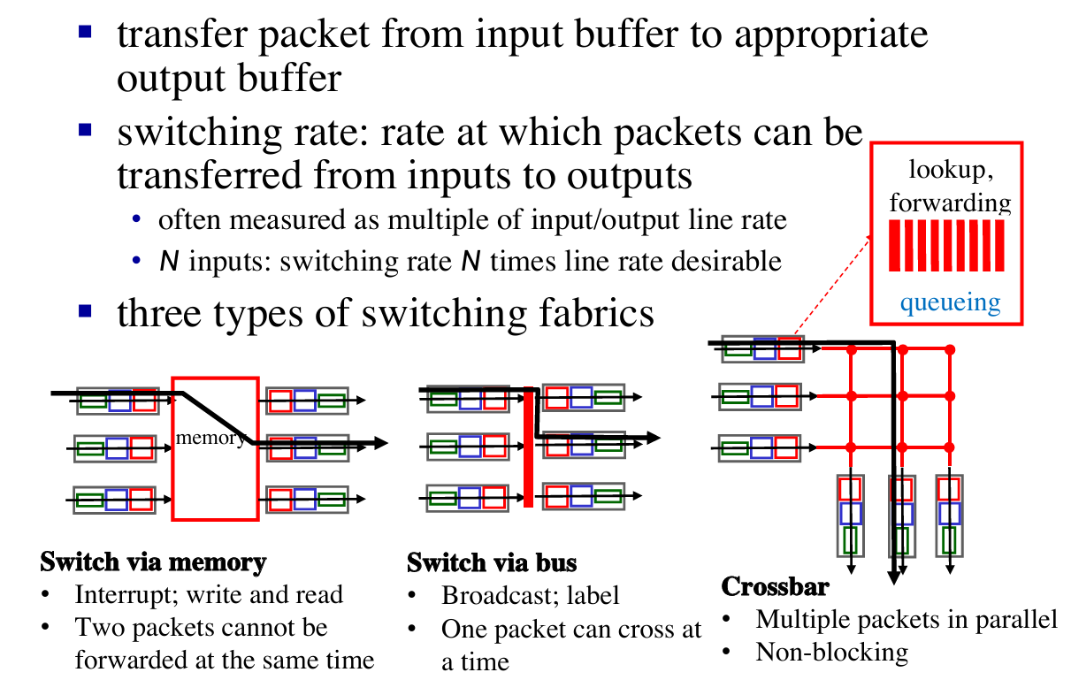
- Switch fabrics
- Output port
- Queuing
- Input port queue
- Output port queue
- Scheduling
Input port & Output port function
Switching Fabrics
Queueing calculation
How much buffering ?
- $RTT \times \text{link capacity } C$
- Recent recommendation: with N flows, buffering = $\frac{RTT \times C}{\sqrt{N}}$
4.3. IP: Internet Protocol
Outline
- datagram format
- fragmentation
- IPv4 addressing
- network address translation
- IPv6
See about network layer

Datagram format
IP fragmentation
- network links have max transmission unit (MTU) - largest possible link-level frame
- different link types, different MTUs
- large IP datagram divided (“fragmented”) within net [类似传输层的分块]
- one datagram becomes several datagrams reassembly
- “reassembled” only at final destination
- IP header bits used to identify, order related fragments
IPv4
Addressing
- IP address: 32-bit identifier for interface of hosts and routers
- Interface: (network interface card) connection between host/router and physical link
- router’s typically have multiple interfaces
- host typically has one or two interfaces (e.g., wired Ethernet, wireless 802.11)
Subnet
- What is a subnet ?
- device interfaces with same subnet part of IP address
- can physically reach each other without intervening router
- each isolated network is called a subnet

E.g. How many subnet here ?
Answer: 6.
How to assign/obtain IP address?
- Classless InterDomain Routing (CIDR)
- A method to assign blocks of IP address
- subnet portion of address of arbitrary length
- address format:
a.b.c.d/x, wherexis # bits in subnet portion of address- e.g. address is
200.23.16.0/23, then the subnet is255.255.254.0
- e.g. address is
- Q1: How does an ISP get block of addresses ?
- A1: ICANN: Internet Corporation for Assigned Names and Numbers
- allocates addresses
- manages DNS
- assigns domain names, resolves disputes
- A1: ICANN: Internet Corporation for Assigned Names and Numbers
- Q2: How does a subnet get block of addresses ?
- A2: gets allocated portion of its provider ISP’s address space
- e.g. ISP’s block is
200.23.16.0/20, then the Organizations IP address can be : 200.23.16.0/23,200.23.18.0/23,200.23.20.0/23…200.23.30.0/23(8 Organizations, 3 bits changed)- Another example to explain this :
- e.g. ISP’s block is
- A2: gets allocated portion of its provider ISP’s address space


- Q3: How does a subnet get block of addresses ?
- DHCP: Dynamic Host Configuration Protocol: dynamically get address from as server
- goal: allow host to dynamically obtain its IP address from network server when it joins network
- can renew its lease on address in use
- allows reuse of addresses (only hold address while connected/“on”)
- support for mobile users who want to join network (more shortly)
- Let’s see how DHCP works in a case :

- DHCP can return more than just allocated IP address on subnet:
- address of first-hop router for client
- name and IP address of DNS sever
- network mask (indicating network versus host portion of address)
NAT (Network Address Translation)
- NAT: reserve blocks of IP addresses for LANs
- private network using private IP addr

- Motivation: local network uses just one IP address
- just one IP address for all devices
- can change addresses of devices in local network without notifying outside world (内部对外部独立)
- can change ISP without changing addresses of devices in local network (外部对内部独立)
- devices inside local network not explicitly addressable, visible by outside world (a security plus)
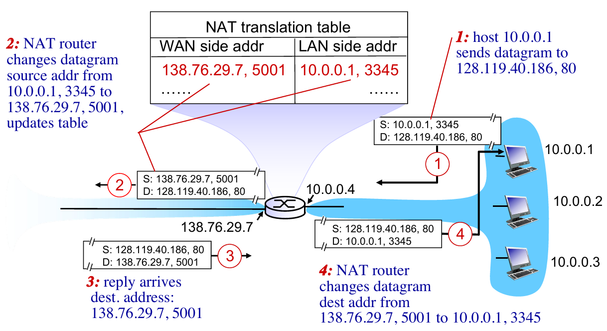
- Implementation:
- Outgoing datagrams: replace
(source IP address, port #)of every outgoing datagram to(NAT IP address, new port #). Remote clients/servers will respond using(NAT IP address, new port #)as destination addr (Not genial addr) - In NAT translation table, record all translation pairs
- Incoming datagrams: replace
(NAT IP address, new port #)in dest fields of every incoming datagram with corresponding(source IP address, port #)stored in NAT table
- Outgoing datagrams: replace
IPv6
Format
- IPv6 using:
- 128-bit address space
- fixed-length 40 byte header
- no fragmentation allowed
Why ?
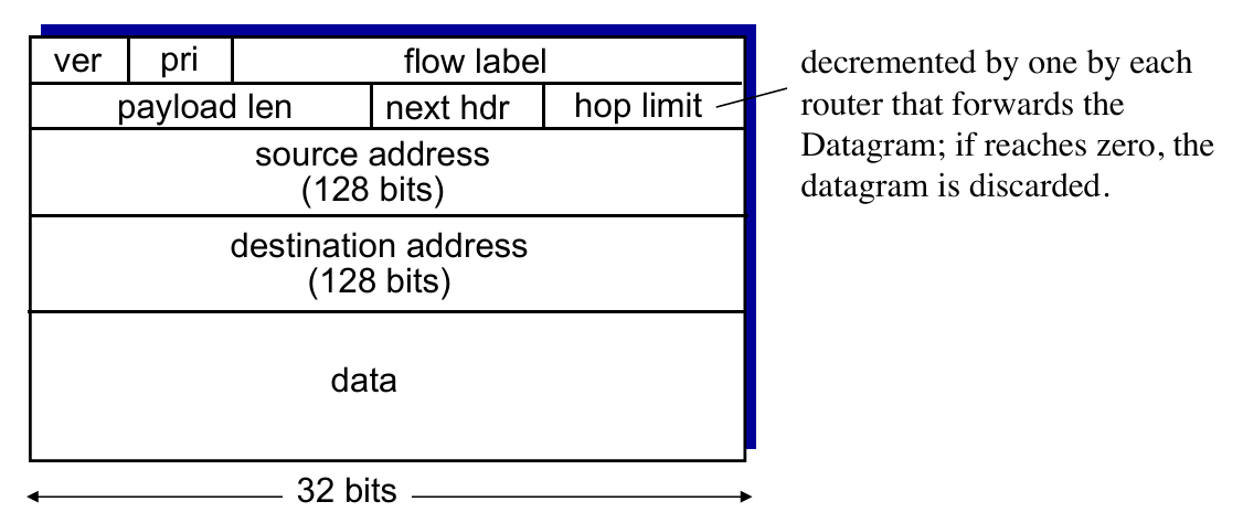
- priority: identify priority among datagrams in flow
- flow Label: identify datagrams in same “flow.” (concept of“flow” not well defined).
- next header: identify upper layer protocol for data (for example, to TCP or UDP).
- Other changes
- checksum: removed entirely to reduce processing time at each hop
- options: allowed, but outside of header, indicated by “Next Header” field
- no fragmentation:
- too large to be forwarded over the outgoing link
- the router simply drops the datagram and sends a “Packet Too Big” ICMP error message
Tunneling
- not all routers can be upgraded simultaneously 👉 mixed IPv4 and IPv6
- Solution – Tunneling: IPv6 datagram carried as payload in IPv4 datagram among IPv4 routers
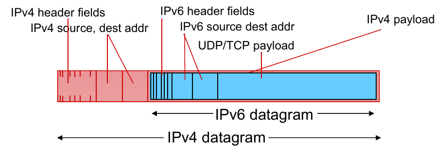
- transfer in routers 👇

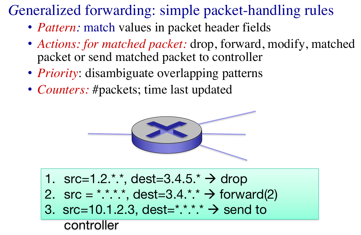
4.4. Generalized Forward and SDN
- Each router contains a flow table that is computed and distributed by a logically centralized routing controller.
- Flow Table defines router’s match & action rules

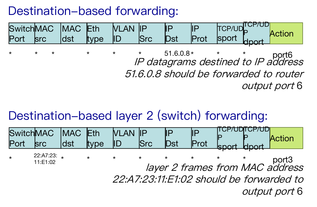
OpenFlow data plane abstraction
 |
 |
 |
 |
- Summary of Openflow
- match+action: unifies different kinds of devices
- Router
- match: longest destination IP prefix
- action: forward out a link
- Switch
- match: destination MAC address
- action: forward
- Firewall
- match: IP addresses and TCP/UDP port numbers
- action: permit or deny
- NAT
- match: IP address and port
- action: rewrite address and port
Chapter 5: Network Layer – The Control Plane
5.1 introduction
5.2 routing protocols
- link state (global)
- distance vector (decentralized)
5.3 intra-AS routing in the Internet: OSPF
5.4 routing among the ISPs: BGP
5.5 The SDN control plane
5.6 ICMP: The Internet Control Message Protocol
5.7 Network management and SNMP
5.1. Intro
Recall: two network-layer functions
forwarding: move packets from router’s input to appropriate router output
(data plane)routing: determine route taken by packets from source to destination
(control plane)
- Two approaches to structuring network control plane:
- per-router control (traditional)
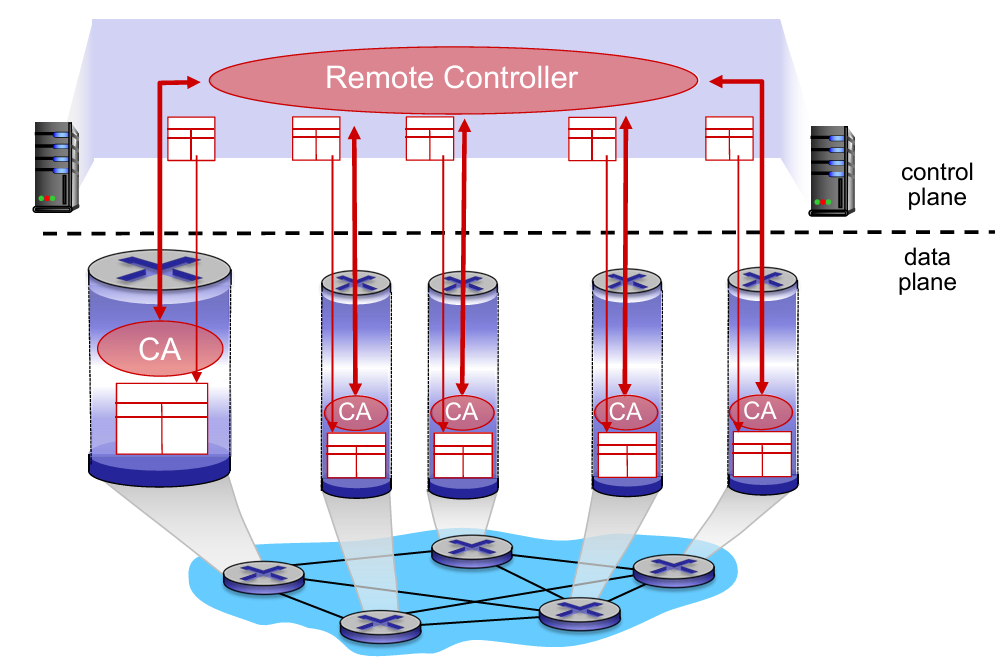
- logically centralized control (software defined networking)
- A distinct (typically remote) controller interacts with local control agents (CAs) in routers to compute forwarding tables
5.2. routing protocols
link state —— getting global info
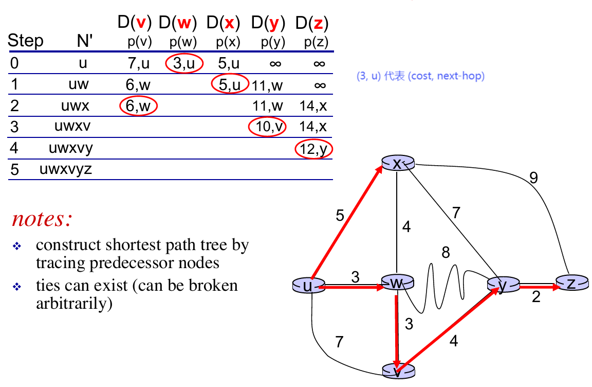
- A linke-state routing algorithm: Dijkstra !!!
1 | Init: |
- An example:
distance vector —— getting decentralized info
- Distributed: each node receives some information from one or more of its directly attached neighbors, performs a calculation, and then distributes the results of its calculation back to its neighbors.
- Iterative: this process continues on until no more information is exchanged between neighbors.
- Asynchronous: it does not require all of the nodes to operate in lockstep with each other.
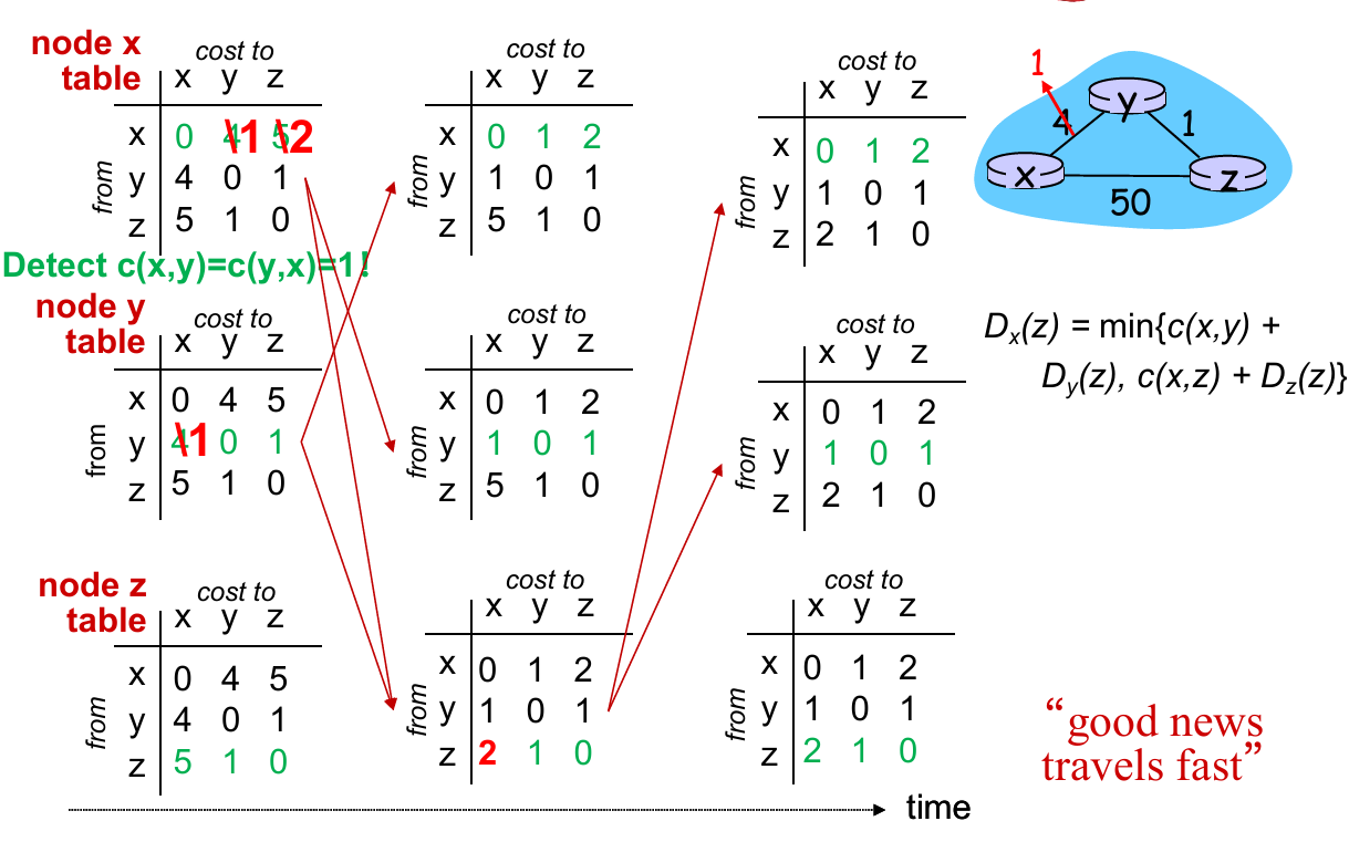
Introduce Bellman-Ford Equation
- $d_{x}(y):=$ cost of least-cost path from $x$ to $y$
- $d_{x}(y)=\min_{v}{ c(x,v)+d_{v}(y) }$
- where $v$ represnets all neighbors of $x$
How this work in DV ?
- Node $x$:
- knows cost to each neighbor $v$: $c(x,v)$
- maintains its recent distance vector $D_x = [D_x(y): y \in N ]$
- maintains its neighbors’ recent distance vectors. For each neighbor $v$, $x$ maintains $D_v = [D_v(y): y \in N ]$
- Key Idea:
- From time-to-time, each node sends its own recent distance vector (DV) to neighbors
- When $x$ receives new DV from neighbor, it updates its own DV using B-F equation
- If its DV has changed, sends the updated DV to neighbors
 |
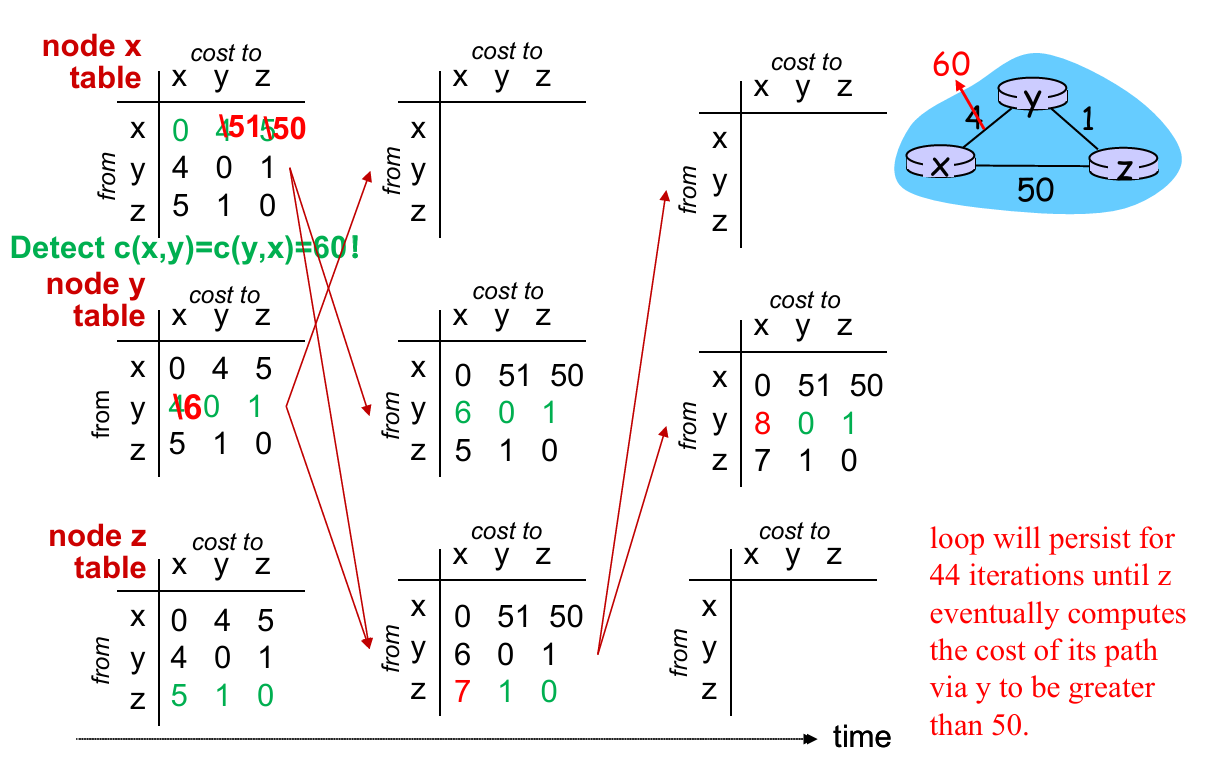 |
Problems: In “good news” (some link cost decrease), the update of forwarding table converge fast (with fewer iterations). But in “bad news” (cost increase), it require more iters to converge the forwarding table!
Solution: Poisoned reverse
- (Example above.) If $Z$ routes through $Y$ to get to $X$ :
- $Z$ tells $Y$ its ($Z$’s) distance to $X$ is infinite (so $Y$ won’t route to $X$ via $Z$)
- However, when there are more than one loop, this method doesn’t work!
Comparison of LS and DV
| Link State | Distance Vector | |
|---|---|---|
| message complexity | with $n$ nodes, $E$ links, $O(nE)$ msgs sent | exchange between neighbors only |
| Speed of convergence | $O(n^2)$ algorithm | time varies(count-to-infinite problem) |
| Robustness | node can advertise incorrect link cost, each node computes only its own table | DV node can advertise incorrect path cost, each node’s table used by others |
5.3. intra-AS routing in the Internet: OSPF
Both LS and DV have problems in practice
We want to make routing scalable
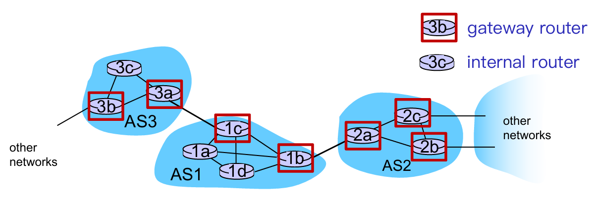
- Solution: aggregate routers into regions known as “autonomous systems” (AS) (a.k.a. “domains”)
- Gateway router: at “edge” of its own AS, has link(s) to router(s) in other AS
- Interior router: no link to other AS
- intra-AS routing
- routing among hosts, routers in same AS (“network”)
- all routers in AS must run same intra-domain protocol
- routers in different AS can run different intra-AS routing protocol
- inter-AS routing
- routing among AS’es
- gateways perform inter-AS routing (as well as intra-AS routing)
Q: How does it function in practice?
A: forwarding table configured by both intra and inter-AS routing algorithm
Intra-AS Routing
- also known as interior gateway protocols (IGP)
- most common intra-AS routing protocols:
- RIP: Routing Information Protocol (distance vector-based)
- OSPF: Open Shortest Path First (link state based)
- IS-IS protocol essentially same as OSPF
- IGRP: Interior Gateway Routing Protocol (Cisco proprietary for decades, until 2016)
Inter-AS Routing will be talked in 5.4
OSPF (Open Shortest Path First)
- “open”: publicly available
- Message format, routing algorithms, link-state broadcast, etc.
- uses link-state algorithm
- link state packet dissemination
- topology map at each node
- route computation using Dijkstra’s algorithm
- router floods OSPF link-state advertisements to all other routers in entire AS
- carried in OSPF messages directly over IP (rather than TCP or UDP)
- Reliable message transfer, link-state broadcast
OSPF “advanced” features
- security: all OSPF messages authenticated (to prevent malicious intrusion)
- Password; private and public key
- multiple same-cost paths allowed (only one path in RIP)
- integrated uni- and multi-cast support:
- Multicast OSPF (MOSPF) uses same topology data base as OSPF
- hierarchical OSPF in large domains.
- Two-level hierarchy: local area, backbone.
- link-state advertisements only in area
- each nodes has detailed area topology; only know direction (shortest path) to nets in other areas.
- Area border routers: routing packets outside the area.
- Backbone routers: run OSPF routing limited to backbone.
- Boundary (gateway) routers: connect to other AS’es.
- Two-level hierarchy: local area, backbone.

5.4. Routing among the ISPs: BGP
5.3 is about intra-AS routing (inside 1 AS), while 5.4 will talk about inter-AS routing (between 2 or more AS)
Overview
- BGP: iBGP, eBGP
- Route Selection
- IP-Anycast
- BGP Routing Policy
BGP
- Each pair of BGP (Border Gateway Protocol) routers (“peers”) exchanges BGP messages over TCP connection:
- advertising paths to destination network prefixes (e.g., X)
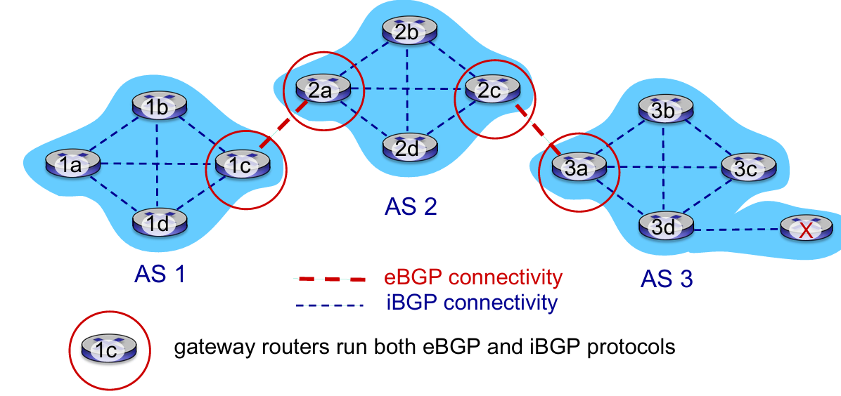
- eBGP: When AS3 gateway router 3a advertises path AS3,X to AS2 gateway router 2c:
- AS3 promises to AS2 it will forward datagrams towards X
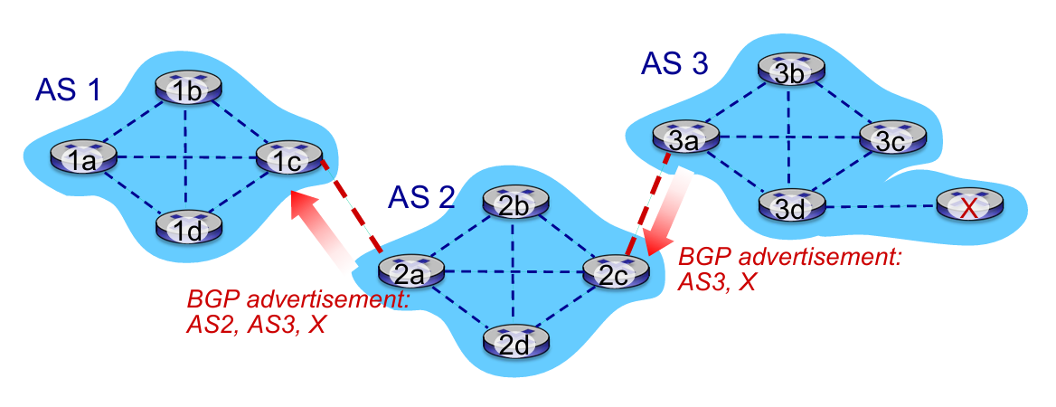
- iBGP: When 1c accept the advertisement from 2a (2a told 1c that “it has a way to X”), 1c will propagate it to all routers in AS1
Q: how does router set forwarding table entry to distant prefix ?
A: Work BGP, OSPF and forwarding table entries together 👇
- E.g.
1dwants to go toX 1a,1b,1dlearn about destXvia iBGP from1c: “path to X goes through 2a (NEXT-HOP)”- to get to
2a-I1, forward over outgoing local interface 1- Intra-AS protocol
Route Selection
Choose route based on one of the severals policies:
- local preference value attribute: policy decision
- shortest AS-PATH
- closest NEXT-HOP router: hot potato routing
- additional criteria
Hot potato routing: choose local gateway that has least intra domain cost (the shortest way to “go out”!)
IP Anycast Service: CDN/DNS

BGP Routing Policy
- policy:
- inter-AS: admin wants control over how its traffic routed, who routes through its net.
- intra-AS: single admin, so no policy decisions needed
- performance:
- intra-AS: can focus on performance
- inter-AS: policy may dominate over performance
- scale:
- hierarchical routing saves table size, reduced update traffic
5.5. The SDN control plane
Recall: SDN logically centralized control plane
A distinct (typically remote) controller interacts with local control agents (CAs) in routers to compute forwarding tables
- Q: Why a logically centralized control plane ?
- easier network management: avoid router misconfigurations, greater flexibility of traffic flows
- table-based forwarding (recall OpenFlow API) allows “programming” routers
- centralized “programming” easier: compute tables centrally and distribute
- distributed “programming” more difficult: compute tables as result of distributed algorithm (protocol) implemented in each and every router
- open (non-proprietary) implementation of control plane
Traffic engineering has difficulties:
- To define path needs to know link weights
- hard to support multi-path routing (balance traffic)
- one switch hard to handle different source to different dst.
- What SDN do ?
- generalized “flow based” forwarding (e.g., OpenFlow)
- control, data plane separation
- control plane functions external to data plane switches
- programmable control applications
Components of SDN controller
- Interface layer to network control apps: abstractions API
- Network-wide state management layer: state of networks links, switches, services: a distributed database
- communication layer: communicate between SDN controller and controlled switches (e.g. OpenFlow)
OpenFlow protocol
- controller-to-switch messages
- configure: controller queries/sets switch configuration parameters
- modify-state: add, delete, modify flow entries in the OpenFlow tables
- Read-state: collect statistics and counter values from the switch’s flow table and ports
- packet-out: controller can send this packet out of specific switch port
- switch-to-controller messages
- packet-in: transfer packet (and its control) to controller. See packet out message from controller
- flow-removed: flow table entry deleted at switch
- port status: inform controller of a change on a port.
5.6. ICMP: The Internet Control Message Protocol
- used by hosts & routers to communicate network level information
- error reporting: unreachable host, network, port, protocol
- echo request/reply (used by ping)
- network-layer “above” IP:
- ICMP msgs carried in IP datagrams
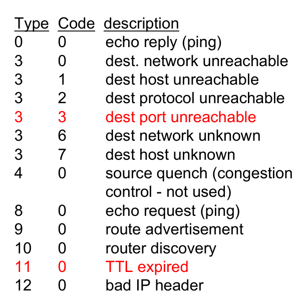
- ICMP message:
- Type + code + the header and the first 8 bytes of IP datagram causing error
Traceroute and ICMP
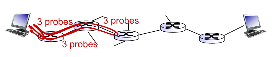
- source sends series of UDP segments to destination
- first set has
TTL = 1 - second set has
TTL = 2, etc. - unlike port number
- first set has
- when datagram in nth set arrives to nth router:
- router discards datagram and sends source ICMP message (type 11, code 0)
- ICMP message include name of router & IP address
- when ICMP message arrives, source records RTTs
- OR traceroute fail: the destination return ICMP “post unreachable” message (type 3, code 3), and source stops.
Summary
What we learn in network layer
- approaches to network control plane
- per-router control (traditional)
- logically centralized control (software defined networking)
- traditional routing algorithms
- implementation in Internet: OSPF, BGP
- SDN controllers
- implementation in practice: ODL, ONOS
- Internet Control Message Protocol
- (network management)
Chapter 6: Link Layer
6.1 introduction, services
6.2 error detection, correction
6.3 multiple access protocols
6.4 LANs
- addressing, ARP
- Ethernet
- switches
- VLANS
6.5 link virtualization: MPLS
6.6 data center networking
6.7 a day in the life of a web request
6.1. Introduction & Services
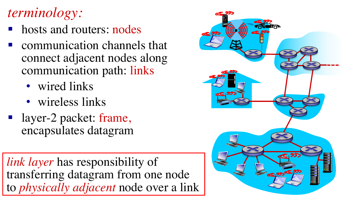
Link layer services
- framing, link access:
- encapsulate datagram into frame, adding header, trailer
- channel access if shared medium
- “MAC” addresses used in frame headers to identify source, destination
- different from IP address!
- reliable delivery between adjacent nodes:
- seldom used on low bit-error link (fiber, some twisted pair)
- wireless links: high error rates
- Q: why both link-level and end-end reliability?
- flow control:
- pacing between adjacent sending and receiving nodes
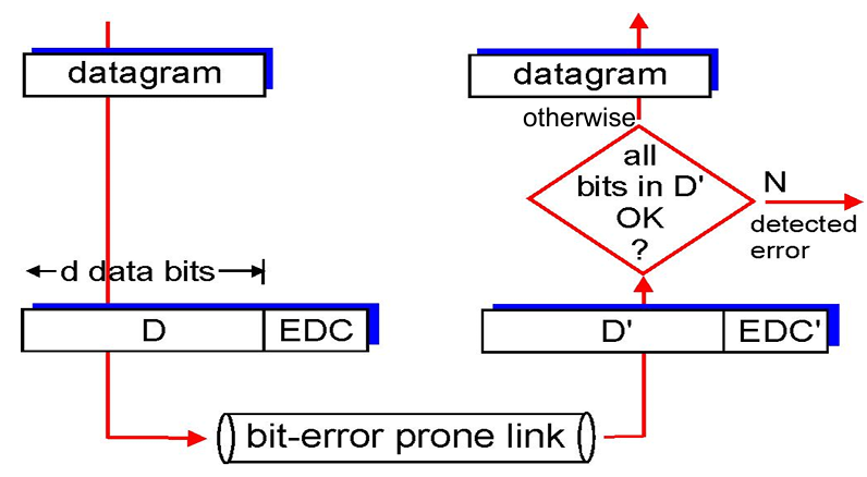
- error detection:
- errors caused by signal attenuation, noise.
- receiver detects presence of errors:
- signals sender for retransmission or drops frame
- error correction:
- receiver identifies and corrects bit error(s) without resorting to retransmission
- half-duplex and full-duplex:
- with half duplex, nodes at both ends of link can transmit, but not at same time
Adaptors Communicating
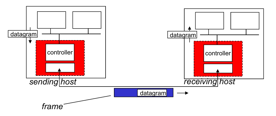
- Sending side:
- encapsulates datagrams in frame
- adds error checking bits, rdt, flow control, etc.
- Receiving side:
- looks for errors, rdt, flow control, etc.
- extracts datagram, passes to upper layer at receiving side
6.2. Error detection & correction
EDC = Error Detection and Correction bits
D = Data protected by error checking, may include header fields
- Parity check
- Check-sum methods (Recall internet checksum)
- Cyclic-redundancy check
Parity Check
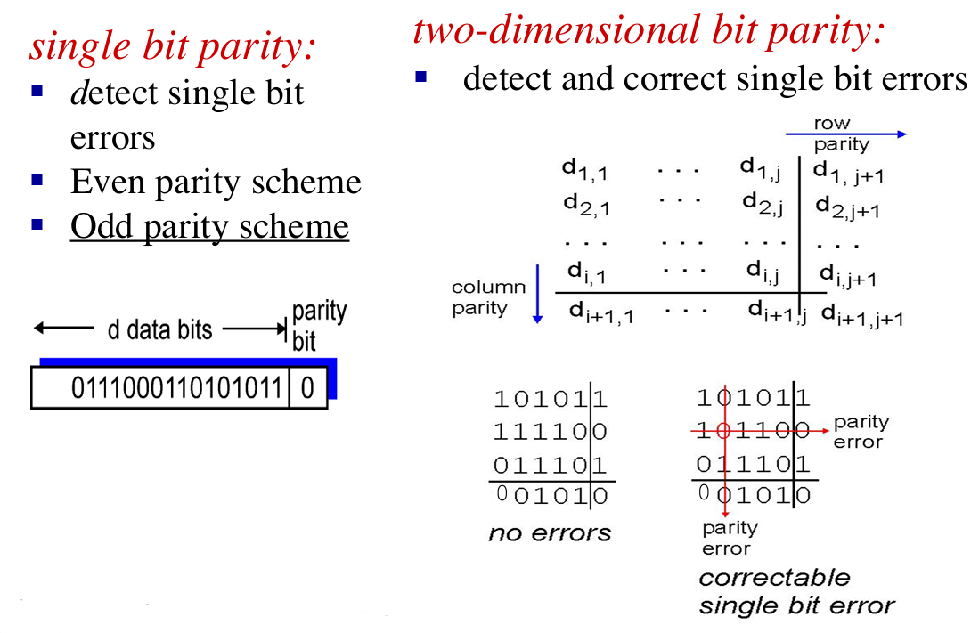
Case 1: one-bit error 👉 good performance;
Case 2: multiple-bits error, but in different lines 👉 some correct bits may be detected as incorrect
Case 3: multiple-bits error in one line 👉 may fail to detect
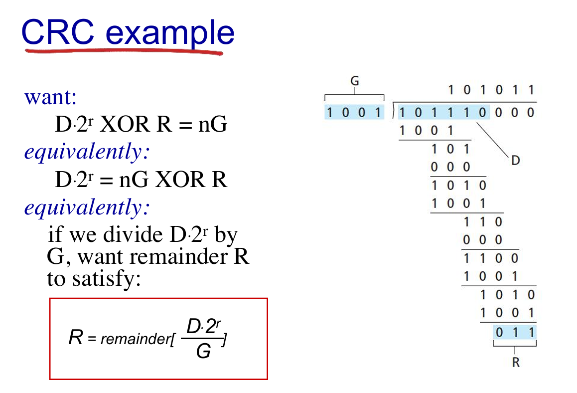
Cyclic redundancy check
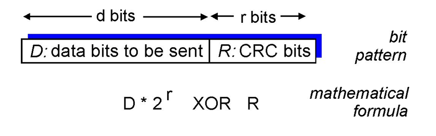
- view
D, and choose (r + 1) bit pattern (generator),G - goal: choose r CRC bits, R, such that
- {D, R} exactly divisible by G (modulo 2)
- receiver knows G, divides {D, R} by G. If non-zero remainder: error detected!
- can detect all consecutive bit errors of r bits or less
- E.g. 👇
6.3. Multiple Access Protocol
2 types of “links”
- point-to-point
- PPP for dial-up access
- point-to-point link between Ethernet switch, host
- broadcast (shared wire or medium):
- old-fashioned Ethernet
- 802.11 wireless LAN (WLAN)
multiple access protocol
- distributed algorithm that determines how nodes share channel, i.e., determine which and when node can transmit
- communication about channel sharing must use channel itself!
- no out-of-band channel for coordination
Ideal MAC
- Given channel of rate $R$ bps, $M$ nodes wanted to transmit can send at rate $R/M$
- Fully decentralized
- no special node to coordinate transmissions
- no synchronization of clocks, slots
- simple
Three broad classes
- channel partitioning:
- divide channel into smaller “pieces” (time slots, frequency, code)
- allocate piece to node for exclusive use
- random access:
- channel not divided, allow collisions
- “recover” from collisions
- “taking turns”:
- nodes take turns, but nodes with more to send can take longer turns
Channel partitioning MAC protocols
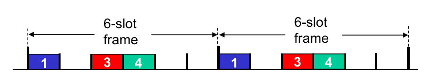
- TDMA (Time Division Multiple Access)
- access to channel in “rounds”
- each station gets fixed length slot (length = packet transmission time) in each round
- unused slots go idle
- example: 6-station LAN, 1,3,4 have packets to send, slots 2,5,6 idle
- FDMA: frequency division multiple access
- channel spectrum divided into frequency bands
- each station assigned fixed frequency band
- unused transmission time in frequency bands go idle
- example: 6-station LAN, 1, 3, 4 have packet to send, frequency bands 2, 5, 6 idle
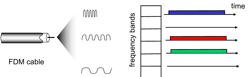
- Limitations:
- sometimes idle but somtimes full (not efficient enough)
Random access protocols
- Random access; if fails, wait for a random time
- two or more transmitting nodes 👉 “collision”,
- random access MAC protocol specifies:
- how to detect collisions
- how to recover from collisions (e.g., via delayed retransmissions)
- Advantage: when node has packet to send
- transmit at full channel data rate R.
- no a priori coordination among nodes
- examples of random access MAC protocols:
- slotted ALOHA
- ALOHA
- CSMA, CSMA/CD (Ethernet), CSMA/CA (802.11) [See at Chap 7]
Slotted ALOHA: example of RAP
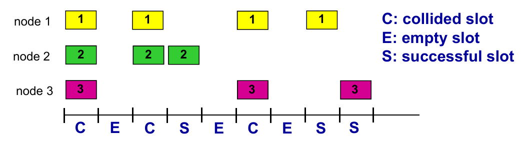
- Operations: when node obtains fresh frame, transmits in next slot
- if no collision: node can send new frame in next slot
- if collision: node retransmits frame in each subsequent slot with probability
puntil success
- Pros
- single active node can continuously transmit at full rate of channel
- highly decentralized: only slots in nodes need to be in sync
- simple
- Cons
- collisions, wasting slots
- idle slots
- clock synchronization
- Suppose: $N$ nodes with many frames to send, each transmits in slot with probability $p$
会算ALOHA的有效传输的效率
CSMA:传输前感知——会遇到collision:传输延迟导致
CSMA+CD (Collision Detection): Lec14 p19
Ethernet CSMA/CD algorithm(了解)
“Taking turns” MAC protocols
look for best of both worlds!
- when one node wants to transmit, it can send at rate $R$.
- when $M$ nodes want to transmit, each can send at average rate $R/M$
概念:master 主机和 slaves 主机
master 轮询(无论 slaves 是否有 frame)
问题:轮询消耗;master 单点错误
另一种方式:token 传输
token 经过节点,有 frame 传 frame,没有直接 pass
问题:token 负载和单点错误
6.4 LANs
概念:lec14 p29
MAC (或 LAN或以太网)地址:适配器(在网络接口)的地址
链路层 switches 没有 MAC 地址
作用:获取“本地”(同一个子网?)的 frame
概念: LAN 地址和 ARP
Lec14 p29:每个 LAN 上的适配器有一个唯一的 LAN 地址
- MAC 地址类似 ID;IP 地址类似邮政编码
- 一个适配器给另一个适配器发送 frame
- 用 dst 的MAC地址封装然后发送到局域网
- 适配器接收到时检查是否匹配,选择是否解封装或丢弃
- MAC 广播地址
FF-FF-FF-FF-FF-FF
Q: How to determine interface’s MAC address, given its IP address?
ARP
Def. Resolve addresses only for interfaces on the same subnet.
- ARP table: each IP node (host, router) on LAN has table
ARP protocol
- same LAN
- broadcast
- diff LAN
- focus on addressing – at IP (datagram) and MAC layer (frame)
- assume A knows B’s IP address, knows IP address of first hop router (e.g. R) or knows R’s MAC address?
- Lec14 p37-p41
Ethernet
- first widely used LAN technology
- simpler, cheap
- kept up with speed race: 10 Mbps – 10 Gbps
概念:bus,star
- 了解:Ethernet frame structure
- Preamble: 7 bytes with pattern
10101010followed by one byte with pattern10101011 - dst / src addresses: 6 byte source, destination MAC addresses
- type: indicates higher layer protocol (mostly IP)
- CRC: cyclic redundancy check at receiver (with error detection)
- Preamble: 7 bytes with pattern
- Connectionless and Unreliable
- no handshaking between sending and receiving NICs
- receiving NIC doesn’t send acks or nacks to sending NIC
- Ethernet’s MAC protocol: unslotted CSMA/CD with binary backoff
Ethernet 有普遍的 MAC 协议和帧格式,但是物理网络(网线/传输速度)不同
Switch
介绍:Ethernet Switch——链路层设备,用于中转帧(含选择)
switch 实现多并发传输
switch 无需人工配置(自学习),维护一个 switch table:(MAC address of host, interface to reach host, time stamp)
自学习例子:终端 A 对应接口 x,终端 B 对应接口(未知),A 往 B 发送帧:
- switch 中未学习到B的接口:往x以外的所有接口输送
- 发现 B 对应接口 x :丢弃帧
- 发现 B 对应接口 y :forward
了解:企业(机构)网络 Lec14 p57
对比 bus/hub,switch 的优势:
- Elimination of collisions (one frame on a time)
- Heterogeneous links (diff link with diff speed)
- Management (disconnect malfunctions NI)
VLANs
Motivation:
- single broadcast domain (效率,安全)
- Inefficient use of switches
Port-based VLAN
- traffic isolation (defined by switch port or MAC addresses)
- dynamic membership
- forwarding between VLANS: done via routing (just as with separate switches)
Q: what if one VLAN over multiple switches ?
A: one trunk port to connect two switches.
6.6 data center networking (略)
6.7 a day in the life of a web request
- connecting to the Internet
- send DHCP to DHCP server, which reply DHCP ACK to endpoint
- get IP address, info of DNS server and first-hop router IP
- ARP: get MAC address of first-hop
- DNS: get IP of
www.google.com, for example - TCP connection carrying HTTP
- HTTP request/reply
Chapter 7. Wireless and Mobile Networks
7.1 introduction
Wireless
7.2 Wireless links, characteristics
- CDMA
7.3 IEEE 802.11 wireless LANs (“Wi-Fi”)
7.4 Cellular Internet Access
- architecture
- standards (e.g., 3G, LTE)
Mobility
7.5 Principles: addressing and routing to mobile users
7.6 Mobile IP
7.7 Handling mobility in cellular networks
7.8 Mobility and higher-layer protocols
7.1 Intro
Elements
- wireless hosts
- base station
- wireless link
7.2 Wireless links
- Characters
- decreased signal strength
- interference from other sources
- multipath propagation
概念:SNR: signal-to-noise ratio
CDMA: Code Division Multiple Access
- unique “code” assigned to each user; i.e., code set partitioning
- all users share same frequency, but each user has own “chipping” sequence (i.e., code) to encode data
- allows multiple users to “coexist” and transmit simultaneously with minimal interference (if codes are “orthogonal”)
- encoded signal = (original data) x (chipping sequence)
- decoding: inner-product of encoded signal and chipping sequence
7.3 IEEE 802.11 Wireless LAN
- 2.4-5 GHz unlicensed spectrum
- up to 11 Mbps
- direct sequence spread spectrum (DSSS) in physical layer
- all hosts use same chipping code
802.11 LAN Architecture: Lec15 p36
Collision Avoidance: RTS-CTS exchange: Lec15 p38 (熟悉流程)
7.4 Cellular Internet access
蜂窝网络
Cell
- covers geographical region
- base station (BS) analogous to 802.11 AP
- mobile users attach to network through BS
- air-interface: physical and link layer protocol between mobile and BS
7.5 Principles: addressing and routing to mobile users
Labs
Week 1
Introduce to Lab 01:
应用层(Application)
ipconfignslookup网络层(Network)
pingtracertnetstat链路层(Link)
arp
-
Protocol layering (TCP/IP)
- Application: HTTP, HTTPS, SMTP, POP3, FTP, DNS, DHCP, etc.
- Transport: TCP, UDP
- Network: IPv4, IPv6, ICMP, IGMP, ARP
- Link
- Physical
-
Domain name(App Layer)
- www.sustech.edu.cn
- www.baidu.com
-
IP address(Network Layer)
- IPv4 (点分十进制)
- 32 bits, dotted decimal notation
- e.g. 192.168.1.1
- IPv6
- 128 bits, hecadecimal notation
- e.g. 2002::4ab8:7b76
- IPv4 (点分十进制)
-
Physical/MAC address(Link Layer)
- 48 bits, hexadecimal notation
- e.g. 8a-69-0c-51-98-66
-
Use
ipconfigto check your PC’s network configurations (Wins)- use
ifconfigin MacOS - IP Address = {Network Number, Host Number}
- Subnet Mask (子网掩码): n ‘1’ + m ‘0’ (totally 32 bits)
- e.g. 255.255.252.0 (22 ‘1’ and 10 ‘0’)
- Network Number = Subnet Mask & IP Address
- e.g. if IP Address is
129.168.1.1and Subnet Mask is255.255.252.0, then Network Number is129.168.0.0and Host Number is0.0.1.1
- e.g. if IP Address is
- use
-
Try
ipconfig -release(haha~)- find your network shutdown! (DHCP disabled)
- use
ipconfig -renewto apply for a new one.
DNS Server
- Try
ipconfig -displaydns: looking for info about network(DNS) cache - Use
ipconfig -flushdnsto clear and refresh the DNS cache
ARP (地址解析协议)
-
arp -a- Display all ARP information, that is, the corresponding relationship between all activated IP addresses and physical
addresses
- Display all ARP information, that is, the corresponding relationship between all activated IP addresses and physical
-
arp -d- Delete all ARP cache contents.
- If the IP address is specified in the command, only the ARP cache information of the IP address is deleted.
-
arp -s- Adding the corresponding relationship between IP address and physical address to ARP cache
- e.g.
arp -s 172.16.0.19 00-10-5C-BE-11-CC
-
nslookupto find the corresponding IP through the host name, or find the corresponding host by specifying the IP.- e.g.
nslookup www.baidu.comornslookup 140.207.198.6
- e.g.
Ping
- Use
pingto check network connectivityping /?: look up usageping -t: ping the specific host 'til stoppedping -i: Time to live(TTL)ping -n <count>: set echo requests number
Tracert: trace route
- Use
tracertto track the routing to check the connectivity of the network. - An example of this(address is fake):
1 | C:\Users\xxx> tracert www.baidu.com |
- Traceroute program: provides delay measurement from source to router along end-end Internet path towards destination. For $i$ in $N$ node($N-1$ routers and 1 end):
- sends three packets (as probes) with a time-to-live (TTL) of $i$; will reach router $i$ on path towards destination
- router $i$ will return packets to sender
- sender times interval between transmission and reply.
Week 2
Wireshark 使用
Week 8
SACK
Review:
- SACK
- Sliding Window
- Retransmission
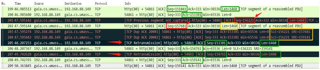
- In practice, while applying SACK, the message often containing “edge” to help clarify the state of pkts
SLE: Left Edge of Block is the first sequence number of this block.SRE: Right Edge of Block is the sequence number immediately following the last sequence number of this block.- Each block represents received bytes of data that are contiguous and isolated; that is, the bytes just below the block, (Left Edge of Block - 1), and just above the block, (Right Edge of Block), have NOT been received.
- E.g. If
Ack = 1461,SLE = 4381, SRE = 5841, it means packet [4381 - 5840] in bytes has been received, the waiting packets is/are [1461 - 4380] in bytes. - E.g. If there is no
SLEorSRE, that meansAckis the lowest bytes unreceived.
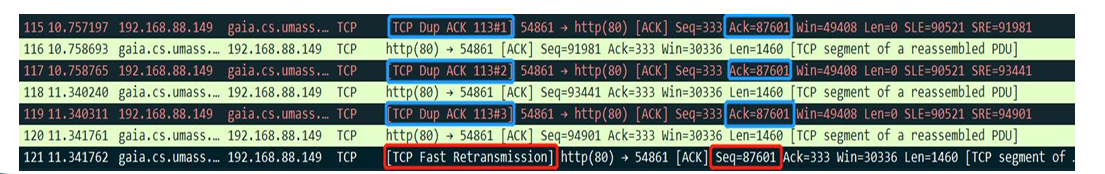
- Retransmission:
- Receiver send immediately
Dup Ackwhen receiving out-of-order pkt. Receiver “wants to tell” sender there is something out-of-order and what it expect (ACK #) - But sender doesn’t know whether the
Dup Ackis caused by pkt loss or reordering of pkts. (Shown above)- Assume it’s reordering pkts, then
Dup Ack #is few (1 or 2), then receiver will generate a newACK - If it’s pkt loss, then there’re moer than 3
Dup Ack, and sender should retransmit theACK #pkt
- Assume it’s reordering pkts, then
QUIC: Quick UDP Internet Connections
Def. A UDP-Based Multiplexed and Secure Transport
Week 11
Use of eNSP
Appendix
| 缩写 | 释义 | 缩写 | 释义 |
|---|---|---|---|
| DSL | 数字用户线 | LAN | 局域网 |
| DSLAM | 数字用户线接入复用器 | WLAN | 无线局域网 |
| HFC(Hybrid fiber coax) | 混合光纤同轴电缆 | WAN | 广域网(无线接入网) |
| ISP | 网络服务提供商 | ARP | 地址解析协议 |
| HTML | 超文本标记语言 | HTTP(S) | 超文本传输(安全)协议 |
| DNS | 域名系统 | CDN | 内容分发网络 |
| URL | 统一资源定位 | SDN | 软件定义网络 |
| NIC | 网络接口卡(网卡) | DHCP | 动态主机配置协议 |
| NAT | 网络地址翻译 | MAC | (Media Access Control) |
| OSPF | Open Shortest Path First | BGP | Border Gateway Protocol |